background image

18

System User Guide Rev. 1.1, NaviVision (Hardware Package to Upgrade Siemens C-Arm) Ver. 1.0

Monitor


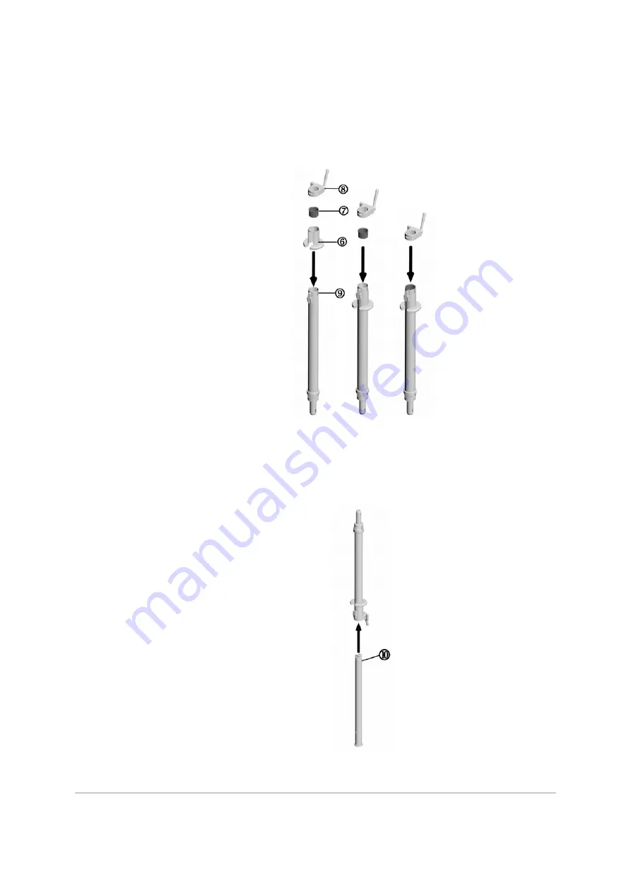
4. Attach the draping sleeve (

6

), guiding sleeve (

7

) and lever assembly (

8

) to the outer tube

(

9

). You will hear a click to indicate the components are correctly positioned on the outer

tube. 

Figure 13: From Left to Right: Attaching the Draping Sleeve, Attaching the Guiding Sleeve and Attaching the 

Lever Assembly to the Outer Tube

5. Turn the inner (

10

) and outer tubes upside down, and carefully slide the inner tube into

the outer tube. 

Figure 14: Slide Inner Tube into Outer Tube

Содержание NaviVision

Страница 1: ...Copyright 2006 BrainLAB AG Germany All rights reserved System User Guide Revision 1 1 NaviVision Hardware Package to Upgrade Siemens C Arm Version 1 0...

Страница 2: ......

Страница 3: ...tion 8 Setup Overview 10 Monitor 11 Overview 11 The Monitor Arm 12 Assembling the Monitor Arm Components 13 Attaching the Monitor to the NaviVision System 20 Mounting the Monitor to the Patient Table...

Страница 4: ...anel 63 Turning on NaviVision On Stand By 63 Turning off NaviVision On Stand By 64 Power Status LED 65 Service LED 65 Transport and Storage 66 Monitor 67 Camera 73 Technical Information 74 Compliances...

Страница 5: ...stered trademarks of Intel Corporation Microsoft and Windows are registered trademarks of Microsoft Corporation ARCADIS is a registered trademarks of Siemens NaviVisionTM is a trademark of BrainLAB AG...

Страница 6: ...ols may be found on the NaviVision system Attention Consult accompanying documents Potential equalization point IPXO Not tested for ingress of water per IEC 529 SN Serial number of instrumentation XXX...

Страница 7: ...used to alert the user to possible injury death or other serious consequences associated with the use or misuse of the equipment Cautions are used to alert the user to the possibility of a problem wi...

Страница 8: ...Vision system components and accessory instrumentation comprise precise mechanical parts which must be handled with care NaviVision system components and accessory instrumentation may only be op erate...

Страница 9: ...nfection and sterilization procedures for the navigation stations the planning and transfer platforms and instrumentation Software User Guides Provide an overview of treatment planning and image guide...

Страница 10: ...6 System User Guide Rev 1 1 NaviVision Hardware Package to Upgrade Siemens C Arm Ver 1 0 System Information...

Страница 11: ...e or on either side left or right of the ARCADIS monitor trolley see from page 32 The monitor can be draped for sterile use by the surgeon Details on the touchscreen drape are provided on page 44 Came...

Страница 12: ...system exhibits a distinct decrease in performance indicating a need for service Liquids leak from the NaviVision system Smoke is emitted by the NaviVision system To prevent electric shock or permane...

Страница 13: ...trolley Air must be allowed to circulate through these slots in order to ensure that the NaviVision system operates properly and does not overheat Do not place the upgraded system near or over a radi...

Страница 14: ...ious positions are possible Figure 2 Possible Camera Setup in the OR 2 Remove the camera protection cover 3 Set up the mobile camera stand page 51 4 Attach the camera to the mobile camera stand page 5...

Страница 15: ...e disposal of this device The NaviVision monitor and touchscreen contain no user serviceable parts All parts and components can only be changed by BrainLAB Support The touchscreen monitor does not com...

Страница 16: ...onitor Arm Components The Monitor Arm Components The monitor arm is comprised of the following components Always hold the curved tube by the plastic handle 3 1 A clamp which is mounted to the rail on...

Страница 17: ...rovided in the Cleaning Disinfection Sterilization Guide The curved tube must be disassembled carefully if disassembly is required as described in the Cleaning Disinfection Sterilization Guide The cur...

Страница 18: ...1 NaviVision Hardware Package to Upgrade Siemens C Arm Ver 1 0 Monitor 1 Insert the spring 1 into the head of the curved tube 2 Figure 5 Insert Spring 2 Insert the bolt 3 into the head of the curved...

Страница 19: ...tion left image in Figure 7 and press it down into the head right image in Figure 7 Figure 7 Left Image Turn Bolt Right Press Bolt into Curved Tube Do not use the curved tube and attached hardware if...

Страница 20: ...sembling the Height Adjustment Module Make sure to assemble the height adjustment module correctly using the proce dure described from below Improper assembly could lead to user or patient in jury or...

Страница 21: ...pening 4 of the lever assembly orienting the thread of the nut toward the thumb screw 5 Figure 11 Insert Lever into Lever Assembly 3 Insert the thumb screw into the lever assembly left image in Figure...

Страница 22: ...be 9 You will hear a click to indicate the components are correctly positioned on the outer tube Figure 13 From Left to Right Attaching the Draping Sleeve Attaching the Guiding Sleeve and Attaching th...

Страница 23: ...the clamp Otherwise the clamp may fall resulting in user or patient injury To avoid malfunction of the device resulting in user or patient injury make sure to properly assemble the clamp components if...

Страница 24: ...Before attaching the monitor to the patient table make sure that the compo nents have been cleaned disinfected and sterilized as described in the Cleaning Disinfection Sterilization Guide Do not moun...

Страница 25: ...16 Attach Clamp to the Side Rail 3 To secure the clamp to the rail turn the clamp screw in a clockwise direction Figure 17 Secure the Clamp Turning the clamp screw counter clockwise will dismantle th...

Страница 26: ...patient table according to standard procedure Figure 18 Drape the Table Left Image Draped Table Right Image Transparent View of Drape 5 Feed the curved tube 2 underneath the drape and insert the tube...

Страница 27: ...ting the tube is correctly positioned and locked Figure 20 Secure the Tube in the Clamp Do not use the curved tube for any purpose other than that certified by BrainLAB Using the tube incorrectly coul...

Страница 28: ...1 0 Monitor 7 Insert the height adjustment module 3 with an integrated rotating joint into the tube This component is used to adjust the height of the monitor arm Figure 21 Insert the Height Adjustme...

Страница 29: ...System User Guide Rev 1 1 NaviVision Hardware Package to Upgrade Siemens C Arm Ver 1 0 25 NaviVision System 9 Lift the module to adjust it to the required height Figure 23 Adjust the Height Module...

Страница 30: ...26 System User Guide Rev 1 1 NaviVision Hardware Package to Upgrade Siemens C Arm Ver 1 0 Monitor 10 Close the lever to secure the height adjustment module in place Figure 24 Close the Lever...

Страница 31: ...gure 25 Attach the Monitor Do not open the lever on the height adjustment module while the monitor is at tached to the adjustment module Otherwise the height adjustment module will slide to the lowest...

Страница 32: ...ure to not accidentally unlock the monitor when adjusting the height of the height adjustment module When moving the monitor arm make sure not to bruise your fingers 12 Feed the connection cable 1 thr...

Страница 33: ...viVision Hardware Package to Upgrade Siemens C Arm Ver 1 0 29 NaviVision System 14 Remove the cap 5 on the drape Figure 28 Fix Drape to the Connector The draped monitor cable is shown in Figure 29 Fig...

Страница 34: ...System User Guide Rev 1 1 NaviVision Hardware Package to Upgrade Siemens C Arm Ver 1 0 Monitor 15 Connect the cable s connector to the monitor sleeve 6 Figure 30 Connect the Cable to the Monitor Slee...

Страница 35: ...System User Guide Rev 1 1 NaviVision Hardware Package to Upgrade Siemens C Arm Ver 1 0 31 NaviVision System 16 The monitor can now be draped with a suitable drape see page 44 Figure 31 Monitor Draped...

Страница 36: ...ens C Arm Ver 1 0 Monitor Mounting the Monitor to the ARCADIS Monitor Trolley Use the following procedure to mount the monitor to the ARCADIS monitor trolley 1 Open the unsterile clamp 1 by turning th...

Страница 37: ...lowed by the lower jaw Make sure that both the upper and lower clamp jaws securely enclose the rail so that the clamp will not slip Figure 33 Mount Clamp to the Rail Do not use the rail on the monitor...

Страница 38: ...re the Clamp Turning the clamp screw counter clockwise will dismantle the clamp causing the clamp components to fall In order to avoid dropping the components if the clamp screw is turned counter cloc...

Страница 39: ...ev 1 1 NaviVision Hardware Package to Upgrade Siemens C Arm Ver 1 0 35 NaviVision System 4 Insert the curved tube 2 into the bottom of the clamp at a 90 angle to the rail Figure 35 Insert the Curved T...

Страница 40: ...tube is correctly positioned and locked Figure 36 Secure the Tube in the Clamp Do not use the curved tube for any purpose other than those certified by BrainLAB Using the tube incorrectly could damag...

Страница 41: ...e to Upgrade Siemens C Arm Ver 1 0 37 NaviVision System 6 Insert the height adjustment module 3 with an integrated rotating joint into the tube This component is used to adjust the height of the monit...

Страница 42: ...38 System User Guide Rev 1 1 NaviVision Hardware Package to Upgrade Siemens C Arm Ver 1 0 Monitor 7 Open the lever 4 on the height adjustment module Figure 38 Open the Lever...

Страница 43: ...System User Guide Rev 1 1 NaviVision Hardware Package to Upgrade Siemens C Arm Ver 1 0 39 NaviVision System 8 Lift the module to adjust it to the required height Figure 39 Adjust the Height Module...

Страница 44: ...40 System User Guide Rev 1 1 NaviVision Hardware Package to Upgrade Siemens C Arm Ver 1 0 Monitor 9 Close the lever to secure the height adjustment module in place Figure 40 Close the Lever...

Страница 45: ...therwise the height adjustment module will slide to the lowest position under the weight of the monitor Do not use the curved tube and attached hardware components without first making sure that the c...

Страница 46: ...sion Hardware Package to Upgrade Siemens C Arm Ver 1 0 Monitor When moving the monitor arm make sure not to bruise your fingers 11 Connect the cable s connector to the monitor sleeve 5 Figure 42 Conne...

Страница 47: ...Vision System Selecting Functions or Buttons To activate a function or a button touch the corresponding button or area using your finger or a blunt tool e g end of a pointer Do not touch the touchscre...

Страница 48: ...field Figure 43 NaviVision Touchscreen Drape Before use check the expiration date on the packaging of the drape If the date has expired the NaviVision Touchscreen Drape must be disposed of To ensure...

Страница 49: ...rape the touchscreen 1 Open the bag containing the touchscreen drape and unfold the blue paper Figure 44 Opening the Touchscreen Packaging 2 Carefully remove the white backing from the drape Figure 45...

Страница 50: ...pgrade Siemens C Arm Ver 1 0 Monitor 4 Pull the drape over the monitor and unroll the drape from the top down Figure 47 Pulling Drape over the Touchscreen 5 Gently pull the edges of the drape down to...

Страница 51: ...6868 and therefore is not intended for diagnostic use Video images are not suitable for diagnostic use as they may appear distorted Only use monitor drapes released by BrainLAB The use of other drape...

Страница 52: ...ep the sterile field only touch the touchscreen where it is covered by the drape Do not touch the drape of the touchscreen using sharp tools Check the expiration date of the touchscreen drape and do n...

Страница 53: ...n page 53 After wards the camera cable must be connected to the Tracking Unit plug of the connector panel see page 60 Make sure that the surface of each lens is clean prior to use To ensure optimum ac...

Страница 54: ...cone in the illustration below indicates the camera field of view Figure 51 Camera Field of View Measurement precision in a plane perpendicular to the viewing direction of the cameras is higher than t...

Страница 55: ...arm has a joint link enabling optimal height adjustment The inte grated swivel head in the camera housing also facilitates adjustment to any angle required Figure 52 Mobile Camera Stand with NaviVisi...

Страница 56: ...obile Camera Stand unattended during surgery Parking Position The initial position of the Mobile Camera Stand is the parking position Always return the Mobile Camera Stand to the parking position when...

Страница 57: ...rface has a spring lock you can only mount the camera if the camera interface is opened Ensure that the two wheel brakes are locked when the Mobile Camera Stand is in parking position Remove the camer...

Страница 58: ...e released the two wheel brakes before moving the Mobile Camera Stand Make sure that you have properly locked the camera spring arm using the cam era release button before moving the Mobile Camera Sta...

Страница 59: ...amera spring arm is locked with the camera arm release button 2 Place the camera 1 into the camera interface 3 so that the spring lock automatically closes Ensure that the camera interface spring lock...

Страница 60: ...rly deploy the camera cable to avoid catching Releasing the Camera Spring Arm Figure 56 Releasing the Camera Spring Arm To release the camera spring arm 1 pull the spring lock 2 backwards Grip the cam...

Страница 61: ...the camera handle the camera will stay in the selected position This is possible as camera and suspension of the spring arm are well balanced When positioning the camera spring arm be careful not to...

Страница 62: ...ized prior to use Figure 58 Putting up the Sterilizable Camera Handle Sleeve Slide the sterilizable camera handle sleeve 2 over the camera handle 1 as far as it will go Make sure that the sterilizable...

Страница 63: ...king position 3 Lock the camera spring arm using the spring lock 4 Unplug the camera cable from the ARCADIS monitor trolley and from the camera kit 5 Grip the camera with one hand 6 Open the camera in...

Страница 64: ...re 60 NaviVision Connector Panel The connector panel contains 1 Mouse Not required for using the NaviVision system For BrainLAB Support only 2 Keyboard Not required for using the NaviVision system For...

Страница 65: ...standards e g IEC 950 for data processing equipment and IEC 60601 1 for medical equipment Furthermore all configu rations must comply with the valid version of the system standard IEC 60601 1 1 Anyone...

Страница 66: ...on Panel is located on the front panel of the ARCADIS monitor trolley Figure 61 Button Panel The Button Panel contains 1 a USB port for loading patient data and saving screenshots see page 63 2 an On...

Страница 67: ...ive application e g when exiting the application copying data or saving screenshots This can damage data on the USB stick or lead to a software crash Loading patient data using the VectorVision naviga...

Страница 68: ...en yellow to indicate that the computer is still running Do not switch off the ARCADIS system during this time in order to not crash the NaviVision system If any problems during the shutdown occur or...

Страница 69: ...isconnected Power Status LED The Power Status LED lights green if the NaviVision system is on lights yellow if the NaviVision system is in stand by mode and the mains power is con nected blinks yellow...

Страница 70: ...ive camera lenses After use follow the below procedure to store the NaviVision system components Shut down and turn off the NaviVision system and unplug all cables Store the monitor in the protective...

Страница 71: ...is stored on the left side of the ARCADIS monitor trolley in a protective compartment To store the monitor 1 Remove the monitor from the monitor arm 2 Carefully push the bolt 1 on the back of the mon...

Страница 72: ...and Storage 3 Place the monitor in the protective compartment on the left side of the ARCADIS monitor trolley by sliding the monitor into place 2 Figure 63 Monitor Storage Compartment Figure 64 shows...

Страница 73: ...DIS monitor trolley 1 in Figure 65 If the monitor was mounted to the patient table sterile procedure see page 20 the fol lowing steps must be performed before the monitor arm can be stored Disassemble...

Страница 74: ...low The same procedure is used to disassemble the monitor arm from the patient table and the monitor trolley 1 Remove the height adjustment module 1 from the curved tube 2 Figure 66 Removing the Heigh...

Страница 75: ...while keeping the button pressed Figure 68 Left Image Press Button Center Image Bring Curved Tube to a 90 Angle Right Image Curved Tube at 90 Angle to the Rail Do not press the unlocking button if the...

Страница 76: ...5 The clamp can now be removed from the rail by turning the clamp screw in a counter clockwise direction Figure 70 Removing the Clamp from the Rail In order to avoid the clamp components falling while...

Страница 77: ...impact dam age Figure 71 Camera Protection Cover Figure 72 Protection Cover on Camera After use follow the below steps to protect the camera Shut down the navigation system Place the protection cover...

Страница 78: ...oval by EN 60601 1 IEC 60601 1 Protection Level I by IEC529 IPX0 Type Plate The type plate is shown in Figure 73 below Figure 73 Type Plates on the ARCADIS Monitor Trolley for the NaviVision System Th...

Страница 79: ...w voltage power supply network that supplies buildings used for domes tic purposes Harmonic emissions IEC 61000 3 2 2000 Class A Voltage fluctuations flicker emissions IEC 61000 3 3 1995 A1 2000 Compl...

Страница 80: ...graded system be pow ered from an uninterruptible power supply or a battery Note Ut is the a c mains voltage prior to application of the test level Power frequency 50 60 Hz magnetic field IEC 61000 4...

Страница 81: ...following symbol a Field strengths from fixed transmitters such as base stations for radio cellular cordless tele phones and land mobile radios amateur radio AM and FM radio broadcast and TV broadcas...

Страница 82: ...le to the signal input or signal output are configuring a medical system and are there fore responsible for ensuring that the system complies with the requirements of IEC 60601 1 1 60601 1 2 If in dou...

Страница 83: ...mum output power of the communications equipment Rated Maximum Output Power of Transmitter W Separation Distance According to Frequency of Transmitter m 150 kHz to 80 MHz 80 MHz to 800 MHz 800 MHz to...

Страница 84: ...sunlight dust salinity and sulfur The system should not be stored at the near vicinity of chemical products or gas To ensure the safe operation of the NaviVision system do not use the system in any e...

Страница 85: ...torage Internal Hard Disk IDE 80 GB Operating System Windows XP Professional Touchscreen Monitor Monitor TFT 1280 x 1024 including wire resistant touch Physical Characteristics 17 Weight 6kg Height 32...

Страница 86: ...em User Guide Rev 1 1 NaviVision Hardware Package to Upgrade Siemens C Arm Ver 1 0 Technical Information Mobile Camera Stand Mobile Camera Stand Weight and Dimensions Weight 33kg Footprint 0 34m Heigh...

Страница 87: ...iVision system components have been dropped or damaged The NaviVision computer exhibits a distinct change in performance indicating a need for service Liquids leak from the NaviVision system Smoke is...

Страница 88: ...s a checkup of all components and functions as well as the safety inspection If a service contract exists BrainLAB will automatically perform the yearly inspection If you do not have a service contrac...

Страница 89: ...u discover a defect switch the NaviVision system off and immediately disconnect from the utility power then contact BrainLAB Support Place a suitable notice such as DO NOT USE on the equipment to prev...

Страница 90: ...arding industrial and non industrial acci dent prevention in the knowledge that these regulations are up to date To inform BrainLAB immediately in writing if the equipment becomes unsafe Safety Inspec...

Страница 91: ...uipment s impedance between the protective earth contact in the main plug and accessible metal parts User Panel Monitor and connectors that are protectively earthed according to clause 18 f of IEC 606...

Страница 92: ...mber of the faulty component which is inscribed on the component A description of the problem The product support specialist will provide you with an estimate for repair or replacement No charges will...

Страница 93: ...nt During installation a hospital representative will oversee the NaviVision system assembly and diagnostic testing and will agree that all products are in working condition BrainLAB is ready to assis...

Страница 94: ...the replacement part 3 Package the faulty part in sufficient packaging material so the part will not sustain fur ther damage 4 Securely tape the box shut 5 Ship the defective product to one of the ad...

Страница 95: ...59 Draping the Touchscreen 45 E Electromagnetic Emissions 75 Electromagnetic Immunity 75 Environmental Requirements 80 NaviVision System 80 F Field of View Camera 50 H Height Adjustment Module Assembl...

Страница 96: ...ition Mobile Camera Stand 52 Positioning Camera 50 Positioning Touchscreen 11 R Reset 61 Return Instructions 90 S Safety Inspection 86 Safety Inspection Form 87 Selecting Functions 43 Separation Dista...

Страница 97: ......

Страница 98: ...www brainlab com Art No 60904 14EN...

Отзывы: