background image

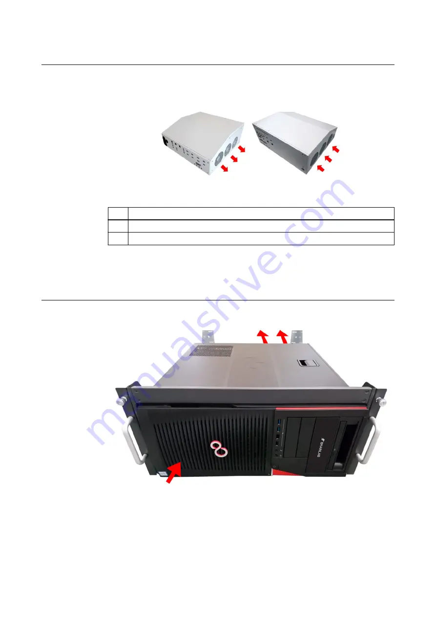
Buzz In-Wall Ventilation Openings

Ventilation openings are located as marked below.

Figure 7  

No.

Component

Computer connection panel

Computer user panel

NOTE: There are no exposed ventilation openings on the In-Wall touch display.


NOTE: The computer must be installed on the bottom/base plate to not block the ventilation
openings.


Digital OR Computer For Barco Ventilation

Figure 8  

Ventilation

26

System and Technical User Guide Rev. 1.2 Buzz Ver. 2.0

Содержание Buzz 2.0

Страница 1: ...BUZZ Version 2 0 System and Technical User Guide Revision 1 2 Date of issue 2020 05 18 ISO 8601 Copyright 2020 Brainlab AG Germany All rights reserved...

Страница 2: ......

Страница 3: ...Proper System Handling 30 2 4 Using the System 32 2 4 1 Turning Buzz On and Off 32 2 4 2 System Messages 34 2 4 3 Touch Display Interaction 36 2 5 System Connections 37 2 5 1 Overview 37 2 5 2 Third...

Страница 4: ...1 Introduction 65 5 1 1 Buzz System 65 5 2 Test Requirements 66 5 2 1 Overview 66 5 2 2 Testing Overview 67 5 2 3 Recurrent Tests 68 5 3 Performing Tests 71 5 3 1 Protective Earth Resistance 71 5 3 2...

Страница 5: ...900 649 115 France and French speaking regions Tel 33 800 676 030 Africa Asia Australia Europe Tel 49 89 991568 1044 Fax 49 89 991568 5811 Japan Tel 81 3 3769 6900 Fax 81 3 3769 6901 Service Life Brai...

Страница 6: ...017 745 the Medical Device Regulation MDR Buzz is a Class I product according to the rules established by the MDR NOTE The validity of the CE label can only be confirmed for products manufac tured by...

Страница 7: ...ent This equipment generates uses and can radiate radio frequency energy and if not installed and used in accordance with the instructions may cause harmful interference to radio communications Operat...

Страница 8: ...damage to device or damage to property Notes NOTE Notes are formatted in italic type and indicate additional useful hints Symbols on Hardware Components The below symbols may be found on the system S...

Страница 9: ...device Risk of electrical shock Class I Laser Risk of injury due to laser radiation Power button Consult the operating instructions Follow the instructions for use U S federal law restricts this devi...

Страница 10: ...Symbol Explanation Handle with care This side up Do not stack more than n Contains renewable materials Symbols 10 System and Technical User Guide Rev 1 2 Buzz Ver 2 0...

Страница 11: ...on and set up prior to use Non sterile usage of videos images and data Shut down and tidying of equipment after surgery A more detailed user profile for the clinical team may depend on the application...

Страница 12: ...atient treatment review the plausibility of all information input to and output from the device Diagnostic Imaging Warning The system has not been tested for diagnostic image quality and may not provi...

Страница 13: ...Intel Management Engine 11 6 0 1042 Nvidia Driver 22 21 13 8541 Realtek audio 6 0 1 8192 Barco Drivers FrGrabber 7 51 32 633 Barco Drivers NIC 7 51 40 664 FTDI driver 2 12 16 0 ESD CAN 6 1 2609 0 IT...

Страница 14: ...ust be verified by a Brainlab service engineer after the first antivirus software installation Be aware that some malware protection software e g virus scanner settings can negatively affect system pe...

Страница 15: ...anged otherwise To create an additional user account for emergency access to the system Step 1 Switch on the system and login as Administrator 2 Open Computer Management by typing the name in Search u...

Страница 16: ...me does not have to match the screenshot below and ensure all the checkboxes are unchecked Enter a password and confirm the password 5 Click Create Software Environment 16 System and Technical User Gu...

Страница 17: ...ure a Standard User Account To install Windows security updates a user must be a member of the group Administrators Add user to the group as described above An Administrator must have a password Autom...

Страница 18: ...ation services and applications Network access controls such as segmentation to limit medical device communication General patch management practices that ensure timely security patch updates on adjac...

Страница 19: ...prolongation is acceptable for the respective patient and treatment Intended Audience This user guide is intended for doctors and hospital staff Reading User Guides This guide describes complex medic...

Страница 20: ...Training and Documentation 20 System and Technical User Guide Rev 1 2 Buzz Ver 2 0...

Страница 21: ...quently Used Functions The following are defined as the most frequently used Buzz hardware functions Switching the device on off Interacting with Brainlab software via the touch display Transferring p...

Страница 22: ...trol room rack for example Figure 1 No Component User panel behind cover Computer including cover Touch display Feature panel NOTE The cables connecting the computer to the touch display are visible w...

Страница 23: ...y and up to three additional touch displays Figure 4 No Component Additional touch display NOTE The Buzz In Wall variant is shown in this example NOTE Depending on your configuration additional touch...

Страница 24: ...System Connections on page 37 System Components 24 System and Technical User Guide Rev 1 2 Buzz Ver 2 0...

Страница 25: ...the top bottom and sides of the system as marked below Figure 5 NOTE If the computer is wall mounted the wave cover must always be mounted Ventilation Openings on Additional Touch Display On Wall Vent...

Страница 26: ...on panel Computer user panel NOTE There are no exposed ventilation openings on the In Wall touch display NOTE The computer must be installed on the bottom base plate to not block the ventilation openi...

Страница 27: ...display be aware that colors may be displayed incorrectly if viewed from an inadequate angle Space for Servicing the System The Buzz touch display can be flipped down 90 when Brainlab services the sys...

Страница 28: ...uitable for use in the presence of flammable anesthetic mixtures containing air oxygen or nitrous oxide Example Buzz On Wall This example shows an installed Buzz On Wall system Figure 9 No Component T...

Страница 29: ...lled Buzz In Wall with additional touch display Figure 10 No Component Touch display Computer compatible with 19 rack Patient environment inside line Additional touch displays SYSTEM OVERVIEW System a...

Страница 30: ...ocks and Impact Protect the device from severe shocks Warning Do not use the system after an abnormal impact e g an earthquake or explosion due to the possibility of fundamental structural damage It i...

Страница 31: ...not try to open enclosures of devices equipped with a laser e g optical disk drives There are no user serviceable components inside Do not operate controls make adjustments or perform procedures to t...

Страница 32: ...in the software preferred or Press the Power button on the Feature Panel 2 Select Shut down in the software When the system has finished shutting down the power LED switches off NOTE After the system...

Страница 33: ...ouch display Step After the computer is completely shut down all additional touch displays will be switched off au tomatically using relay control NOTE The mains power disconnection of Buzz depends on...

Страница 34: ...ing Screen Figure 14 Status LED Feature Panel Figure 15 Color Status Explanation Off Off System is turned off standby Green Flashing System is booting Wait until LED is solid before use Solid System i...

Страница 35: ...ins Power LED Blue Solid Mains power on system standby Power Switch LED Off Off Mains Power LED Blue Solid System switched on Power Switch LED NOTE For a description of LEDs used by the Digital OR Com...

Страница 36: ...as this may disturb the touch functionality Non Sterile Touch Display Use Buzz can be used non sterilely by using fingers to interact with the software Figure 17 No Stroke Type Common Functions Single...

Страница 37: ...dently of Buzz e g bypassing Buzz and connecting the signal directly to a monitor Warning Additional equipment connected to medical electrical equipment must comply with the respective IEC or ISO stan...

Страница 38: ...to CD R CD RW DVD R DVD R DL DVD RW DVD RAM 4 7GB DVD R DVD R DL DVD RW Only insert standard CD DVDs of 120 mm diameter Do not insert irregularly shaped CD DVDs Related Links Introduction on page 65 S...

Страница 39: ...onnect IEC compliant devices to the LAN ports Wireless LAN Connections Buzz is compliant with the following CE FCC IC The WLAN module included in this product cannot be accessed by the end users The F...

Страница 40: ...100 104 108 112 116 132 136 140 149 153 157 161 165 802 11b g 1 11 Europe 802 11a 36 40 44 48 52 56 60 64 100 104 108 112 116 120 124 128 132 136 140 802 11b g 1 13 Japan 802 11a 36 40 44 48 Known as...

Страница 41: ...el The areas encircled on the connection panel contain connection ports of a similar function Multiple third party video connections are possible at the same time NOTE For a description of the front a...

Страница 42: ...is inter face might damage the devices or the MCU 2 x DVI Video Inputs Power connections for transfer line components 6 x 5V DC 2A NOTE Only connect equipment specified by Brainlab to the DC output Ne...

Страница 43: ...Feature Panel Brainlab support Hospital Network 1 GbE Brainlab support Hospital Network 10 GbE Not in use Brainlab support Audio In Out Microphone In Audio In Audio Out Brainlab support Video Output...

Страница 44: ...Pin are not accessible if the Computer is wall mounted The connections 4 11 in the connection panel are only for use by Brainlab support Do not change or add any connections to this panel as they are...

Страница 45: ...e system is optional When connecting POAG an ME System is created NOTE Not applicable to the Digital OR Computer For Barco Integration which is placed outside the OR in a non medical room How to Conne...

Страница 46: ...Potential Equalization Connection 46 System and Technical User Guide Rev 1 2 Buzz Ver 2 0...

Страница 47: ...ilization Do not sterilize Buzz components No Liquids Do not spray cleaning solvents or other liquids directly into electrical interfaces or openings e g the air vents Ensure that liquid does not ente...

Страница 48: ...nfection wipes or cleaning procedures others than those specified may damage equipment It is suggested to only use disinfectants verified by Brainlab to avoid damaging the system Cleaning Intervals Cl...

Страница 49: ...Buzz In Wall with silicone joint IP44 Computer All variants IP20 NOTE The Ingress Protection depends on the Buzz Display installation For more details please refer to the Buzz 2 Site Planning Manual I...

Страница 50: ...f the device Altitude Considerations Unless stated otherwise the system is rated for use at an altitude less than 3000 meters Transport or store the system at an altitude less than 6000 meters Adaptio...

Страница 51: ...zz In Wall Buzz In Wall Touch Display Additional Touch Display In Wall Height 667 mm 667 mm Width 1189 mm Buzz 42 Touch Display only 1054 mm Depth 103 mm Depth in wall 98 mm 103 mm Depth in wall 98 mm...

Страница 52: ...computer Digital OR Computer For Barco Integration without Rack Mount Computer Height 186 mm 7 3 inch Width 430 mm 16 9 inch Depth 481 mm 18 9 inch Weight 18 kg 40 lbs NOTE The above dimensions are ba...

Страница 53: ...ements Computer Touch Display Digital OR Computer For Barco Integration Operating Voltage 100 240 V 100 240 V 100 240 V Current 8 4 A 3 5 1 5 A 9 5 4 0 A Frequency 50 60 Hz 50 60 Hz 50 60 Hz Power Con...

Страница 54: ...k may introduce new risks and require additional analysis Changes to the hospital network include Changes to the hospital network configuration Connecting additional items to the hospital network Disc...

Страница 55: ...listed in this section Patient treated incorrectly due to Network failure during patient data transfer Malware e g viruses causing PC to miscalculate data Unwanted exposure of the patient to anesthet...

Страница 56: ...ch CISPR 11 class B is normally required this equipment might not offer adequate protection to radio frequency communication services The user might need to take mitigation measures such as relocating...

Страница 57: ...st transi ent burst input a c power port IEC 61000 4 4 2 kV 100 kHz repetition fre quency 2 kV 100 kHz repetition fre quency Electrical fast transi ent burst signal in put output ports 1 kV 100 kHz re...

Страница 58: ...Pulse modula tion 18 Hz 1 8 0 3 27 450 430 470 GMRS 460 FRS 460 FM 5 deviation 1 kHz sine 2 0 3 28 710 704 787 LTE Band 13 17 Pulse modula tion 217 Hz 0 2 0 3 9 745 780 810 800 960 GSM 800 900 TETRA...

Страница 59: ...800 MHz d 1 2 P 800 MHz to 2 5 GHz d 2 3 P 0 01 d 0 12 d 0 12 d 0 23 0 1 d 0 38 d 0 38 d 0 73 1 d 1 20 d 1 20 d 2 30 10 d 3 79 d 3 79 d 7 27 100 d 12 00 d 12 00 d 23 00 For transmitters rated at a ma...

Страница 60: ...ia DVI Copper cables and DVI EO converter may be used for signal in and out Always fix the screws to lock the cable connector NOTE Use high quality DVI copper cable max 5 m to connect DVI Sources or a...

Страница 61: ...Port 1 2 ca ble max 5m for 1920 x 1080 60 Hz and max 3 6 m for 3840 x 2160 30 Hz 60 Hz Digital OR Computer For Barco Integration Compatible Cables and Connectors Port Example Handling USB USB ports fo...

Страница 62: ...0i 29 97 HD SDI 720p 50 720p 60 1080i 30 1080i 60 1080p 25 1080p 30 3G SDI 1080p 50 1080p 59 94 1080p 60 DVI In 8 Bit RBG DVI I Single Link DVI D 640x480 60Hz 800x600 60Hz 1024x768 60Hz 1280x720 60Hz...

Страница 63: ...20x1080 60Hz Microscope 8 Bit RGB DVI I Single Link DVI D 1920x1080 60Hz RGB YCbCr DVI I RGB YCbCr 1024x768 60Hz 1280x1024 60Hz Graphic Card 3D Output The graphic card delivers a progressive single st...

Страница 64: ...Impedance n a fiber Supported Video Output Connectors Displays Connectors Signal Type Impedance Ohm Display 1 Display Port DisplayPort 1 2 TheDisplayPort 100 Display 2 Display 3 Display 4 Display 5 DV...

Страница 65: ...against electric shock Refers to electrical equipment in which protection against electric shock does not rely on basic insulation only but which includes an additional safety pre caution in that mean...

Страница 66: ...ut the use of a tool must be tested individually Additionally the ME SYSTEM must be tested as a whole to avoid that an aging component causes unacceptable values If items of ME EQUIPMENT that are comb...

Страница 67: ...void the validity of previous reference values Test Guidelines When performing recurrent tests Perform required test steps in the order defined below All tests must be passed before the device can be...

Страница 68: ...he interior are not ac ceptable Verify the condition of all cables shipped used with the device such as Mains power cable Ethernet cable Video cables USB cables Microscope connection cable if applicab...

Страница 69: ...l use Power on the device Check if indicator lights are working Start a software application If applicable verify the desired function of the ME SYSTEM Check that Data is displayed on the screen Touch...

Страница 70: ...rent Device under test Buzz 2 Serial number Serial number of measuring device Calibration valid through date Test performed date by Related Links System Messages on page 34 Performing Tests on page 71...

Страница 71: ...f the display is not accessible from the outside contact Brainlab support Protective Earth Resistance Test Point Tested Measured Val ue Test Passed Buzz Computer only Housing screw close to Mains Powe...

Страница 72: ...r your Buzz variant Equipment Leakage Point Tested Measured Val ue Test Passed Computer measurement point on power button Screw of DVI I Out on computer user panel On wall Frame only Right bot tom hol...

Страница 73: ...uch Display In Wall Frame overview of potential measurement points In wall Frame measurement de tail On Wall Frame only Additional Touch Display at the paint free hole on the frame ELECTRICAL SAFETY S...

Страница 74: ...the measurement points as defined for equipment leakage current Point Tested Measured Val ue Test Passed Screw of DVI I Out on computer user panel Computer measurement point on power button On wall F...

Страница 75: ...Test Passed In wall Frame measurement de tail On Wall Frame only Additional Touch Display at the paint free hole on the frame USB Port on the Feature Panel ELECTRICAL SAFETY System and Technical User...

Страница 76: ...Touch Current 76 System and Technical User Guide Rev 1 2 Buzz Ver 2 0...

Страница 77: ...are allowed to repair the system and equipment Risk of electrical shock There are no user serviceable parts Do not remove any covers All installation servicing and maintenance is to be carried out by...

Страница 78: ...n Yes Automatically performed by Brainlab No Contact Brainlab support for arrangement Scope This inspection covers all components and functions as well as the items specified on the safety inspection...

Страница 79: ...with product safety information and product instructions and has read and understood the user guides Is up to date with current local regulations regarding industrial and non industrial accident preve...

Страница 80: ...d in the electrical safety form In addition to the electrical safety form the safety inspection also comprises the further inspections described under Maintenance Related Links Test Requirements on pa...

Страница 81: ...em emits smoke If an LCD panel is damaged e g broken glass do not allow any escaping liquid to come into contact with skin mucous membranes eyes mouth or foodstuffs Do not inhale vapors If contact occ...

Страница 82: ...irchheim Heimstetten Germany Brainlab Inc RMA Dept 5 Westbrook Corporate Center Suite 1000 Westchester IL 60154 USA Brainlab KK RMA Dept Tamachi East Bldg 2F 3 2 16 Shibaura Minato ku Tokyo 108 0023 J...

Страница 83: ...54 F FCC compliance 7 functional earth resistance 71 G guides 19 I inspections 77 annual 78 safety 79 M manuals 19 O operating conditions 50 P panels connection panel 41 protective earth resistance 7...

Страница 84: ......

Страница 85: ......

Страница 86: ...brainlab com Art No 60920 19EN 60920 19EN...

Отзывы: