


The brake clutch is splined to the primary sun gear shaft
between the motor and the primary sun gear. It will
allow this shaft to turn freely in the direction to raise a
load, and lock up to force the brake discs to turn with
the shaft in the direction to lower a load. (See figures 5
& 6).
The hydraulic brake cylinder, when pressurized, will
release the spring pressure on the brake discs, allowing
the brakes discs to turn freely.
Please note that this static load holding brake is only
released in the direction of lowering a load.
The auxiliary brake system consists of the following
components:
1. Multi-disc, spring-applied brake cylinder assembly
2. Brake shaft
3. Pressure reducing valve
4. Shuttle Valve
The auxiliary brake is coupled directly to the hoist drum
by the brake shaft. The brake cylinder assembly
requires hydraulic pressure to force the brake piston
against the brake springs to relieve the spring force and
release the brake. The shuttle valve allows oil to be
applied to the auxiliary brake in both hoisting and lower-
ing directions, without affecting the static brake in the
hoisting direction. The pressure reducing valve limits
the hydraulic pressure from the hydraulic system to the
brake cylinder assembly. It is factory preset to 1000 PSI
(6,900 kPa) and requires no adjustment.
D
UAL
B
RAKE
S
YSTEM WITH
A
UXILIARY
B
RAKE
- O
PERATION
When hoisting a load, the brake clutch, which connects
the motor shaft to the primary sun gear, allows free rota-
tion of the gear train. The sprag cams lay over and per-
mit the inner race to turn free of the outer race. (See fig-
ure 5). The friction brake remains fully applied, but the
shuttle valve allows oil to the auxiliary brake to release
the brake. For extremely light loads (such as in empty
hook conditions), some slight scrubbing of the auxiliary
brake plates may occur. The fully applied static brake
has no effect on the hoist during lifting operations.
When the lifting operation is stopped, the load attempts
to turn the primary sun gear in the opposite direction.
This reverse input causes the sprag cams to instantly
roll upward and firmly lock the shaft to the fully applied
static brake. (See figure 6).
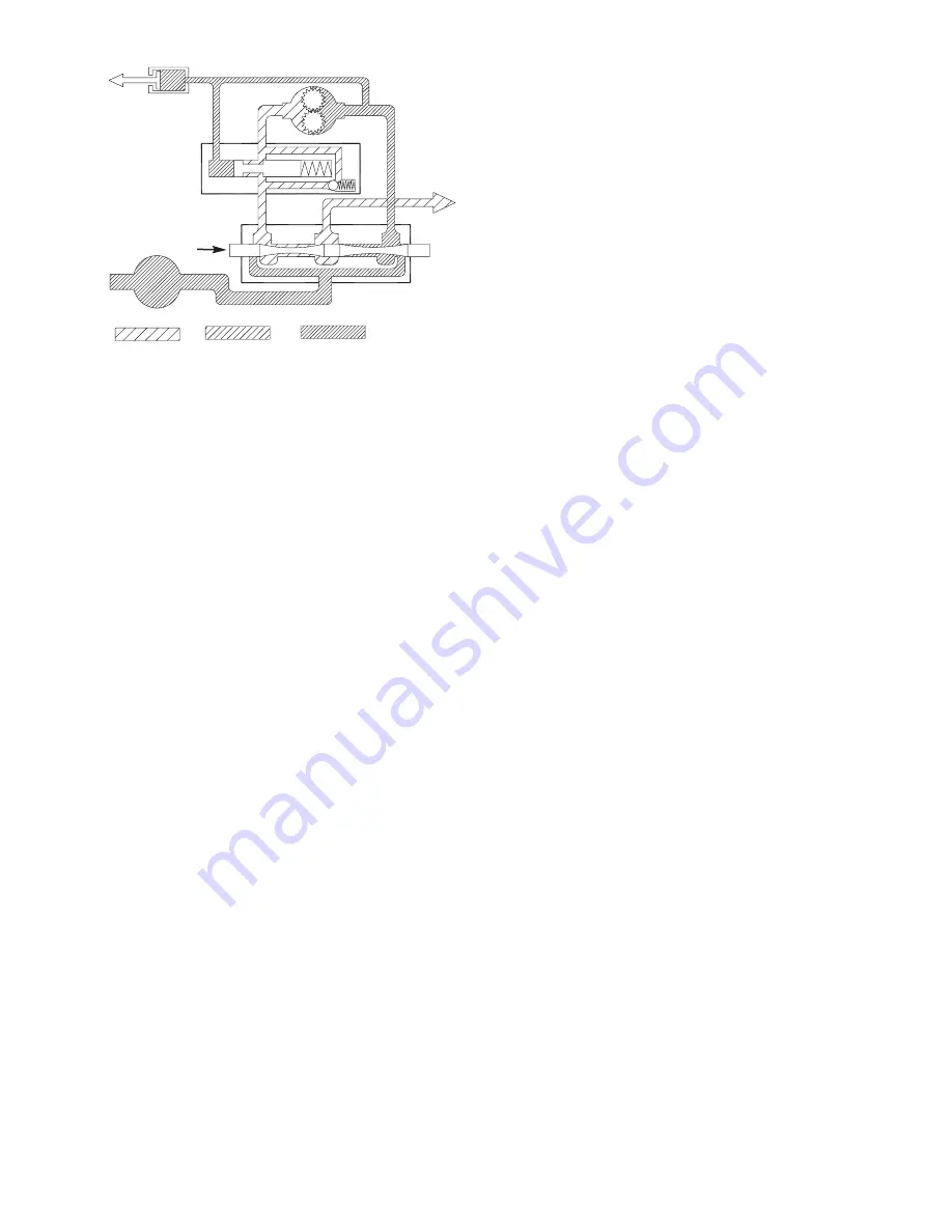
When the hoist is powered in the lowering direction, the
motor cannot rotate until there is sufficient pilot pressure
to open the brake valve. (See figures 3 & 4). The stat-
ic friction brake will completely release at a pressure
lower than that required to open the brake valve, typi-
cally 400 - 450 PSI (2,760 - 3,100 kPa) and 600 -700
PSI (4,140 - 4,830 kPa) respectively. The extent to
which the brake valve opens will determine the amount
of oil that can flow through it, and the speed at which the
load will be lowered. Increasing the flow of oil to the
hoist motor will cause the pressure to rise causing the
brake valve opening to enlarge, speeding up the
descent of the load. Decreasing this flow causes the
pressure to lower and the opening in the brake valve to
decrease in size, thus slowing the descent of the load.
When the control valve is shifted to neutral, the pres-
sure will drop and the brake valve will close, stopping
the load. The static friction brake will engage and hold
the load firm after the brake valve has closed.
When lowering a load very slowly for precise position-
ing, no oil flow actually occurs through the hoist motor.
The pressure will rise to a point where the brake will
release sufficiently to allow the load to rotate the motor
through its own internal leakage. This feature results in
a very slow speed for extremely accurate positioning.
The friction brake receives very little wear in the lower-
ing operation. All of the heat generated by the lowering
and stopping of a load is absorbed by the hydraulic oil,
where it can be readily dissipated.
During both lifting and lowering operations, the auxiliary
brake will open to allow the drum to operate. In the lift-
ing direction, the shuttle valve diverts the oil flow away
from the static hoist brake and allows the release of the
auxiliary brake. The pressure required to completely
release the auxiliary brake is 400 - 450 PSI (2,760 -
3,100 kPa). During lowering, the oil from the brake
valve is sent to both the static brake and the auxiliary
brake, allowing both brakes to be released simultane-
ously. This action assures that both brakes are released
before the brake valve opens, further assuring that
dynamic braking takes place within the brake valve.
6
Pump
Brake
Valve
Static
Brake
Motor
Control
Valve
Low Pressure Medium Pressure High Pressure
To
Tank
Figure 4


