
Boxfish ROV Owner’s Manual
V1.3. All rights reserved. Information and specifications may change at any time without notice.
p92
20
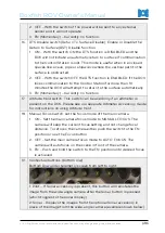
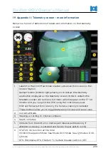
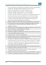
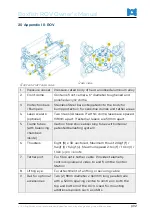
Appendix III: ROV
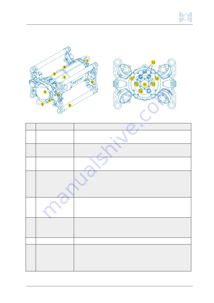
Front and left side view
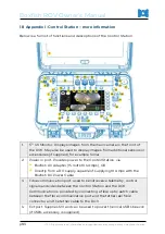
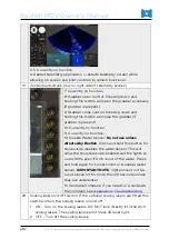
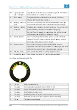
Rear view
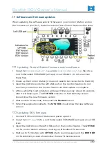
1.
Pressure vessel Pressure-rated body of hard anodised aluminium alloy
2. Front dome
Contains front camera. 6" diameter toughened and
polished acrylic dome
3. Protection bars
/ Bumpers
Stainless Steel bars integrated into the body for
bump protection for sensitive domes and tether areas
4. Laser scalers
(optional)
Two Class 3R lasers. If within dome, lasers are spaced
138mm apart. If external, lasers are 50mm apart.
5. Frame tubes
(with balancing
chambers
inside)
Carbon fibre shock absorbing tubes with internal
patented ballasting system
6. Thrusters
Eight (8) x 3D vectored, Maximum thrust 20kgf (f) /
14kgf (l) / 14kgf (v). Maximum speed 2.1kn (f) / 1.3kn (l) /
1.3kn (v) kn = knots
7. Tether port
For fibre optic tether cable. Provides telemetry,
control signals and video to and from the Control
Station
8. Lifting eye:
For attachment of a lifting or securing cable
9. Rail for optional
accessories
Two (2) 8mm diameter x 460mm long parallel rails
with a 52mm spacing centre to centre on both the
top and bottom of the ROV. Used for mounting
additional sensors such as USBL.


