


4-3
190 Montauk
Section 4 • Electrical System
R
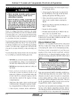
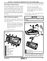
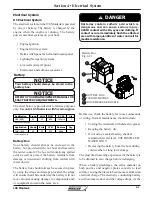
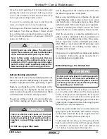
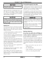
The battery switch, located on the component board
on the forward wall of the console interior, allows
you to control the delivery of DC power from the
battery to the engine as well as allowing the alternator
to charge the battery. Your battery selector switch
has two settings, “ON” and “OFF”, “ON” gives you
power from the battery. “OFF” you have no power
to the engine. Remember to turn the battery selector
switch to “ON” before you attempt to start your
engine.
NOTE: The bilge pump cannot be turned off with the
battery selector switch.
Battery Switch
Fig. 4.3.1
12 Volt Accessory Receptacle
Your boat is equipped with a 12 volt accessory
receptacle located on the aft wall of the console
storage tray (See fig. 2.10.1). It is a DC (cigarette
lighter) style receptacle to be used with any 12 volt
accessories using this type of plug. The receptacle is
made of corrosion resistant marine grade materials
and has a moisture proof cap. The receptacle is
protected by a 10 amp fuse located in the fuse box
on the upper aft wall of the console interior..
Be sure
to use accessories that do not exceed the rated
capacity of the circuit, (10 amps) or the breaker
will trip.
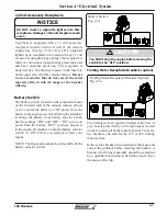
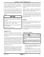
NOTICE
DO NOT insert a cigarette lighter into this
receptacle. Damage to the unit & system could
occur.
You MUST stop the engine before moving the
switch to the “OFF” position.
!
CAUTION
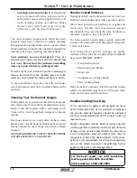
Battery Switch
DC MAIN
ELEC. MAIN
BILG
E
ACC
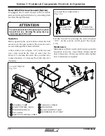
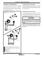
Trolling Motor Receptacle Breakers (Option)
Fig. 4.3.2
Trolling Motor Receptacle Breakers (option)
DC MAIN
ELEC. MAIN
BILG
E
ACC
The trolling motor receptacle located at the bow of
your boat is protected by a 40 amp breaker located
on the forward wall of the console interior. There are
two breakers, one each for the 12V or 24V trolling
motor system.
In the event a breaker trips, determine the cause and
correct the problem before resetting the breaker. A
breaker which trips repeatedly should be examined
by a qualified electrician to determine and correct
the cause of the trip.
Содержание 190 Montauk
Страница 1: ...190 Montauk Owner s Manual ...
Страница 43: ...1 22 190 Montauk Section 1 Safety R THIS PAGE INTENTIONALLY LEFT BLANK ...
Страница 69: ...2 26 190 Montauk Section 2 General Information R THIS PAGE INTENTIONALLY LEFT BLANK ...
Страница 81: ...3 12 190 Montauk Section 3 Systems Components Overview Operation R THIS PAGE INTENTIONALLY LEFT BLANK ...
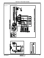
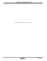
Страница 87: ...4 6 190 Montauk Section 4 Electrical System R Switch and Breaker Panel Schematic Fig 4 6 1 ...
Страница 88: ...4 7 190 Montauk Section 4 Electrical System R Switch and Breaker Panel Schematic Fig 4 7 1 ...
Страница 89: ...4 8 190 Montauk Section 4 Electrical System R THIS PAGE INTENTIONALLY LEFT BLANK ...
Страница 103: ...5 14 Section 5 Care Maintenance R 190 Montauk THIS PAGE INTENTIONALLY LEFT BLANK ...