


2-18
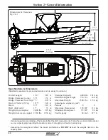
190 Montauk
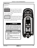
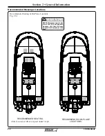
Section 2 • General Information
R
NOTICE
Refer to the Trolling Motor Owner’s Manual for
the correct size and type of battery.
If equipped, the trolling motor receptacle is located
at the bow of the boat. The panel is wired for 12V &
24V and includes a 12V accessory receptacle. Your
boat has reinforced areas of the bow that will make
it easier to mount a trolling motor. The reinforced
sections are located on either side of the bow
navigation light and extend back along the gunwale.
The phenolic material can be drilled and tapped to
hold machine screws.
There are a variety of trolling motors and mounts
that can be fitted to your boat. See your Boston
Whaler
®
dealer or talk to a reputable trolling motor
dealer for the right type and size of trolling motor
and battery that will work best with your boat.
When looking for a trolling motor you will need to
know the distance from the top of the deck to the
waterline.
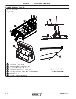
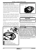
In addition to the trolling motor receptacle panel,
your boat will have a removable bow light (See
fig. 2.10.1) which replaces the standard bow light,
an additional battery boxes located in the console
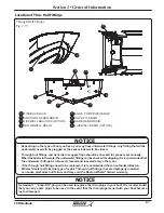
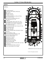
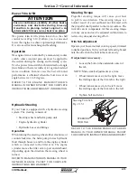
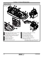
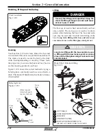
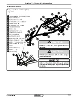
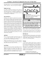
Trolling Motor Panel (Option)
Fig. 2.18.1
Trolling Motor Panel (Option)
1
2
3
REINFORCED BOW
TROLLING MOTOR PLUG
TROLLING MOTOR RECEPTACLE
12 VOLT ACCESSORY RECEPTACLE
4
1
2
3
4
Refer to
Section 4 • Electrical System, page 4-3
for
additional information regarding the trolling motor
electrical hookup.
There is a risk of electrical shock. Always
have a qualified marine electrician install any
system upgrades that are not already installed
on your boat. There are a variety of wiring
configurations up to 36Volts. Incorrect wiring
will adversely affect your trolling motors
performance. Always use the correct circuit
protection and wire gauge when installing an
upgraded trolling motor wiring system.
!
WARNING
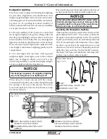
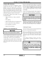
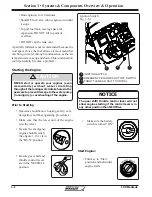
Trolling motor (Option)
Fig. 2.18.2
REFER TO THE MANUFACTURER’S MANUAL IN
YOUR OWNER’S MANUAL PACKET FOR COMPLETE
INSTRUCTIONS AND WARRANTY.
interior, plus two (2) 40 amp breakers located on the
component board in the center console which can be
accessed through the door on the port side.
Содержание 190 Montauk
Страница 1: ...190 Montauk Owner s Manual ...
Страница 43: ...1 22 190 Montauk Section 1 Safety R THIS PAGE INTENTIONALLY LEFT BLANK ...
Страница 69: ...2 26 190 Montauk Section 2 General Information R THIS PAGE INTENTIONALLY LEFT BLANK ...
Страница 81: ...3 12 190 Montauk Section 3 Systems Components Overview Operation R THIS PAGE INTENTIONALLY LEFT BLANK ...
Страница 87: ...4 6 190 Montauk Section 4 Electrical System R Switch and Breaker Panel Schematic Fig 4 6 1 ...
Страница 88: ...4 7 190 Montauk Section 4 Electrical System R Switch and Breaker Panel Schematic Fig 4 7 1 ...
Страница 89: ...4 8 190 Montauk Section 4 Electrical System R THIS PAGE INTENTIONALLY LEFT BLANK ...
Страница 103: ...5 14 Section 5 Care Maintenance R 190 Montauk THIS PAGE INTENTIONALLY LEFT BLANK ...


