Bosch Worcester Danesmoor 12/14 Скачать руководство пользователя страница 2

1.1 

General installation information and advice may be obtained

from  the  Oil  Firing  Technical  Association  for  the  Petroleum
Industry  (OFTEC).  Training  courses  are  also  offered  by  OFTEC,
leading to inclusion on their list of registered engineers.

1.2 

The appliance should be installed by a competent person. The

person installing the appliance should be aware of the Health and
Safety at Work Act and take appropriate action to ensure that the
regulations  are  adhered  to.  In  order  to  give  optimum  efficiency
and trouble free operation the appliance should be commissioned
by a qualified engineer. OFTEC recommends the use of registered
engineers for the commissioning of oil-fired burners.

1.3 

The manufacturers notes must not be taken, in any way, as

overriding statutory obligations.

1.4 

The  compliance  with  a  British  Standard  does  not,  of  itself,

confer  immunity  from  legal  obligations.  In  particular  the  installa-
tion  of  this  appliance  must  be  in  accordance  with  the  relevant
requirements of the following British Standards and regulations in
respect of the safe installation of equipment.
BS 5410: part 1& 2: Code of practice for Oil Fired Boilers.
BS 799: part 5: Specification for Oil Storage Tanks
BS 7593: Code of practice for treatment of water in domestic hot
water central heating systems.
BS  5449:  part  1:  Specification  for  forced  circulation  hot  water
central heating for domestic premises.

BS  5955:  part  8:  Specification  for  the  installation  of
thermoplastic  pipes  and  associated  fittings  for  use  in  domestic
hot and cold water services and heating systems.
BS 7291: Thermoplastic pipes and associated fittings for hot and
cold  water  for  domestic  purposes  and  heating  installations  in
buildings.
BS  7074:  part  1:  Application,  selection  and  installation  of  expan-
sion vessels and ancillary equipment for sealed water systems.
BS 7671: IEE Wiring Regulations current edition.

The Building Regulations Part J and L1 England and Wales; Part F
Section III and Part J Scotland; Part L and Part F Northern Ireland.
Local water company bye-laws.
The Control of Pollution (Oil) Regulations.

1.5 

To  ensure  that  the  installation  will  perform  to  the  highest

standards, the system and components should conform to those
mentioned in the  instructions.

The 

Benchmark

initiative is the new code of practice

to  encourage  the  correct  installation,  commissioning  and
servicing  of  domestic  central  heating  boilers  and  system
equipment.

The  'Log-book'  is  a  vital  document  that  must  be  completed
by the installer at the time of installation. It confirms that the
boiler has been installed and commissioned according to the
manufacturers instructions.

Without the completion of the Log-book, manufacturers may refuse
to respond to a call-out from a householder, who will be advised
that he or she must call back the installer, who has not fulfilled his
obligations to record the information required by the initiative.

It is important that:

The services and the system are properly flushed as specified.
The User is clearly instructed on the correct operation of the
appliance.
The benefits of regular servicing are explained - to maintain the
efficiency and extend the life of the appliance.
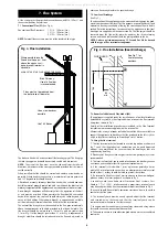
2.1 

These instructions cover both conventional flue (CF)/low-level

discharge (LLD) and room sealed balanced flue (RS) appliances.

2.2 

The Worcester Danesmoor range of appliances covered in

these instructions have been designed to serve domestic central
heating and hot water requirements ranging from 12 kW to 25 kW.

2.3 

The  RS  balanced  flue  appliance  forms  a  fully  room  sealed

system  by  surrounding  the  burner  with  a  unique,fully  sealed,
push  fit  box.  This  causes  the  combustion  air  to  be  drawn
through a factory sealed air duct formed at the rear and under-
side  of  the  boiler.  The  sealed  burner  cover  gives  excellent
acoustic noise reduction and alleviates the need for an air brick
to be located in the boiler room.
Because  the  balanced  flue  system  does  not  rely  on  the  cabinet
panels to form the room seal, combustion readings can be taken
from the flue outlet plate as on a conventional appliance, and the
cabinet panels can be easily removed during installation thereby
preventing any damage.

2.4 

The boiler is factory set to the mid range output and can be

altered, if necessary, by adjusting the burner as specified in Tables
2 to 4. The low level discharge and room sealed models are only
suitable for use with 28 second Kerosene heating oil. 

NOTE:  It  is  a  mandatory  requirement  of  the  building
regulations that only 28 second kerosene is used on low level
discharge flues. 
2.5 

The  conventional  flue  15-19  and  20-25  models  may  be

converted to burn 35 second gas oil by changing the nozzle and
burner settings as specified in Tables 3 and 4.

2.6 

A colour coordinated twin channel programmer can be fitted

to the appliance facia panel. This is available from Worcester Heat
Systems as an optional extra.

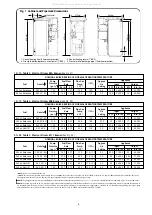
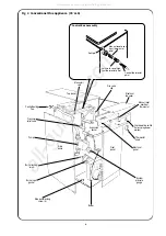
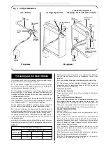
2.7 Principle appliance components. See Figs. 2 and 3.
Oil Fired Burner

A  fully  automatic  oil  fired  pressure  jet  burner  is  used  to  supply
heat  to  the  boiler.  The  burner  can  be  set  to  the  output  require-
ments as detailed in Tables 2 to 4.

Pump

An integral circulating pump is incorporated within the appliance
casing. The pump speed may be altered to suit the heating load by 

2. General Information

1. Installation Regulations

2

1.

Installation Regulations ...........................................Page   2

2.

General Information .................................................Page   2
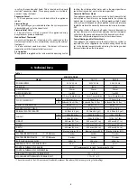
3.

Technical Data...........................................................Page   3
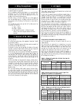
4.

Siting the Appliance .................................................Page   5

5.

Removal of the Cabinet............................................Page   5

6.

Air Supply..................................................................Page   5

7.

Flue System...............................................................Page   8

8.

Oil Supply ..................................................................Page 11

9. Heating and Hot Water System...............................Page 13

10. Electrical ....................................................................Page 15
11. Installation ................................................................Page 19
12. Commissioning .........................................................Page 20
13. Instructions to the User ...........................................Page 23
14. Routine Cleaning and Inspection............................Page 23
15. Fault Finding .............................................................Page 25
16. Short Parts List..........................................................Page 26

Contents

All manuals and user guides at all-guides.com

Содержание Worcester Danesmoor 12/14

Страница 1: ...ater and Central Heating 12 14 MINIMUM 12 kW 41 000 Btu h MAXIMUM 14 kW 48 000 Btu h 15 19 MINIMUM 15 kW 51 000 Btu h MAXIMUM 19 kW 65 000 Btu h 20 25 MINIMUM 20 kW 68 000 Btu h MAXIMUM 25 kW 85 000 Btu h THESE INSTRUCTIONS APPLY TO UK MODELS ONLY THESE INSTRUCTIONS ARE TO BE LEFT WITH THE APPLIANCE All manuals and user guides at all guides com a l l g u i d e s c o m ...

Страница 2: ...as not fulfilled his obligations to record the information required by the initiative It is important that The services and the system are properly flushed as specified The User is clearly instructed on the correct operation of the appliance The benefits of regular servicing are explained to maintain the efficiency and extend the life of the appliance 2 1 These instructions cover both conventional...

Страница 3: ...r circumstances Central Heating and Hot Water Mode The appliance will supply heat to the central heating system as required The water supplied to the central heating circuit can be set to the desired temperature by adjusting the heating control thermostat located on the facia panel SPECIFICATIONS Model 12 14 15 19 20 25 POWER SUPPLY 230V 50 Hz 230V 50 Hz 230V 50 Hz IP RATING IP 20 IP20 IP 20 HEATI...

Страница 4: ... kW Btu hr kW Btu hr Output Kg h l h 28 Sec Kerosene 0 50 60 ES 110 1 40 1 77 215 10 5 8 5 17 58 000 15 51 000 28 Sec Kerosene 0 55 80 EH 115 1 59 2 01 225 10 5 8 75 19 65 000 17 58 000 28 Sec Kerosene 0 60 60 ES 105 1 78 2 25 235 11 5 9 0 21 5 73 000 19 65 000 35 Sec Gas Oil 0 50 80 S 155 1 80 2 12 235 11 5 9 0 21 5 73 000 19 65 000 NOMINAL BOILER RATING AT NORMAL OPERATING TEMPERATURE 15 19 Tabl...

Страница 5: ...efficient combustion an adequate supply of air must be delivered to the combustion chamber To provide sufficient air a suitable inlet should be provided into the room or space in which the boiler is situated the sizes of which are given in Table 5 An air brick or other form of continuous air supply may have to be built into the installation in order to ensure an adequate supply of air 6 2 If the a...

Страница 6: ...screw Pressure relief valve Central heating flow Pump Burner Front panel Expansion vessel Electrical panel User operating switch Optional programmer position Top panel Thermostat knob Fire valve clip Manual reset over heat thermostat phial Automatic reset high limit thermostat phial Control thermostat phial Split pin Control Box Assembly All manuals and user guides at all guides com a l l g u i d ...

Страница 7: ...e relief valve Central heating flow Pump Burner Front panel Expansion vessel Electrical panel User operating switch Optional programmer position Top panel Thermostat knob Fire valve clip Burner cover Rear air duct Rear air duct access cover Manual reset over heat thermostat phial Automatic reset high limit thermostat phial Control thermostat phial Split pin Control Box Assembly All manuals and use...

Страница 8: ...terminal arrangement 7 3 Room Sealed Balanced Flue Model RS The appliance is supplied ready for installation as a low level discharge balanced flue system by the simple addition of one of the flue terminal kit options shown in Fig 6 Details of the installation procedure are included in the Flue Terminal Installation instructions supplied with the terminal kit Alternatively a range of room sealed b...

Страница 9: ...Discharge 4 to 7 Single Skin Wall For use with non standard single skin walls up to 182 mm thick Where noise emission from the flue terminal is likely to be of concern it is recommended that the standard 12 in terminal is used and the appliance stood away from the wall to take up the extra terminal body length c Rear Discharge Extension Kit 12 to 36 Wall X For use where the wall thickness exceeds ...

Страница 10: ...nal facing the terminal Not allowed 1200 K Vertically from a terminal on the same wall Not allowed 1500 L Horizontally from a terminal on the same wall Not allowed 750 M Above an intersection with the roof 600 Not applicable 732 N From a vertical structure on the side of the terminal 750 Not applicable 750 O Above a vertical structure less than 750mm from the side of the terminal 600 Not applicabl...

Страница 11: ...b The oil supply pipe should be laid as level as possible to avoid air pockets and unnecessary friction losses c The following components should be fitted in the fuel line between the storage tank and burner 1 A manual isolating valve installed as close to the tank as possible 2 A fire valve in accordance with BS5410 as shown in Fig 10 The fire valve should be fitted externally with a fire detecti...

Страница 12: ...um Fire valve to BS 5410 Fire valve to BS 5410 Isolating valve Isolating valve Fire detection element Filter Burner Burner Wall Wall b Double pipe system Isolating valve Non return valve Non return valve Fire detection element Isolating valve Oil tank c Single pipe lift system with de aerator Fire valve to BS 5410 H 3 5 m 11 5 ft maximum Burner Wall Fire detection element De aerator H 3 5 m 11 5 f...

Страница 13: ...tems when all of the radiators are fitted with thermostatic radiator valves 9 5 The pressure jet burner fitted to the appliance has full auto matic control and hence there is no requirement for heat leak radiators 9 6 Any unused boiler tappings should be plugged prior to filling 9 7 The primary system should be flushed and treated in accordance with the recommendations of BS 7593 before the system...

Страница 14: ...The filling point must be at low level and must never be a permanent direct fixing to the mains water supply 9 16 Water loss must be replaced See Fig 13 The connection should be made to the central heating return as close to the appliance as possible 9 17 The make up vessel where fitted must be fitted with a non return valve 9 18 Repeated venting loses water from the system It is essential that th...

Страница 15: ...16a A plug in colour co ordinated 2 channel electronic programmer is available from Worcester Heat Systems Limited Full instructions covering installation and operation of the programmer are included with the kit The programmer will give fully independent central heating CH and hot water HW programmes when the switch on the rear of the unit is set to P If an external programmer is to be fitted to ...

Страница 16: ...ations having pumped circulation to both the domestic hot water and radiator circuits The domestic hot water and radiator circuits are independently controlled by two motorised valves via a cylinder thermostat and a room thermostat Both thermostats switch the water circulator and the boiler on and off 10 9 Honeywell Y Plan See Fig 19 The Y Plan provides complete control on installations having pum...

Страница 17: ... 1 to 3 and link 2 to 4 and make link 3 to 4 10 WAY JUNCTION BOX NOTE If a frost thermostat is required it can be wired to the remote junction box NOTE The 10 way junction box must be a terminal block type and current rated to at least 5 amps Remote Pre wired Junction Box OUTSIDE BOILER INSIDE BOILER 7 8 910 X External Pump disconnect and remove Pump supplied in boiler NOTE Optional Worcester Prog...

Страница 18: ...ve link 1 to 3 and link 2 to 4 and make link 3 to 4 Grey White Blue Brown Room thermostat Pump supplied in boiler N E NL HEAT SYSTEMS HEATING ADVANCE OFF TWICE ONCE ON OFF TWICE ONCE ON SELECT LOCK SET YES SELECT PM TUE HOT WATER ADVANCE Burner Socket Optional Worcester Programmer Cylinder Thermostat C 1 2 Mid Position Valve Honeywell V4073A E N L N E E N 1 2 3 4 5 6 7 8 9 1112131415 10 Blue Brown...

Страница 19: ...ith the open grommet supplied in the plastic bag 4 Slacken the pipe retaining clip screw located directly below the grommet hole When using 12mm copper pipe replace the clip with the larger one supplied 5 Bend a piece of 10mm or 12mm copper tube as selected to the correct profile to allow the pipe to be fed down the side of the appli ance Make a slight chamfer on the end of the pipe to be fed thro...

Страница 20: ... using a 5mm Allen key Note It is important that a good seal is made between the burner and the boiler to prevent re circulation of the flue gases from the combustion chamber to the burner inlet or the room in the case of a CF LLD appliance 3 On the RS balanced flue model feed the electrical lead back through the hole in the burner surround housing and fit the grom met into the hole ensuring a sea...

Страница 21: ...e correctly located If the baffles are correctly located then reduce the pump pressure since nozzle variations of up to or 15 may occur 12 15 Remove the oil pressure gauge and manifold and check all oil system joints for any signs of leakage 12 16 On the RS balanced flue model fit the burner cover box supplied in the flue terminal kit by lining up the four ball studs and the polarising pin in the ...

Страница 22: ... nozzle line and rotate the adjusting disc one turn anti clockwise to move forward by 1 mm Output Dimension kW Head Type A 15 PL 6 7 21 5 10 3 mm 17 PL 6 7 21 5 10 5 mm 19 PL 6 7 21 5 10 5 mm Fig 22 Electro Oil Inter B11 Burner 20 25 model Combustion Head Air control indicator Photocell Air adjustment screw 4 mm hexagonal head Transformer Control box Oil pump Pressure adjustment screw Draught tube...

Страница 23: ... 2 Pre Service Check 1 Remove the cabinet front and top panels as described in Section 5 2 On the RS balanced flue model remove the burner cover box as described in Section 5 5 3 Operate the appliance and system noting any faults which may need to be corrected during the service 14 3 Cleaning the Burner IMPORTANT Disconnect the electrical supply at the mains before commencing any servicing Turn of...

Страница 24: ...e of a CF LLD appliance 14 4 Remove the paper element from the external oil filter and replace If the filter contains a washable element then thoroughly clean in Kerosene or white spirit and re assemble into the filter 14 5 Clean the air ducts RS balanced flue model only 1 Remove the rear duct top cover 2 Shine a light down the rear duct and inspect both the rear and under duct for any sign of deb...

Страница 25: ...ogrammer open circuit Check by linking 8 and 9 on the connector Faulty control box Replace if necessary Flue draught incorrect Check flue draught Combustion settings incorrect Set up as in installation instructions Faulty nozzle Replace nozzle HIGH SMOKE NUMBER Faulty nozzle Replace nozzle Incorrect combustion settings Readjust as in installation instructions Oil pressure incorrect Adjust to recom...

Страница 26: ...ox Base Satronic S01 S701 1 8 716 142 782 0 Ignition Electrode 1 8 716 142 752 0 Motor B9 AEG or Simel 70 W 1 8 716 156 597 0 Motor B11 AEG FHP 90W 1 8 716 142 732 0 Oil Pump B9 Danfoss BFP41L3 1 8 716 142 743 0 Oil Pump B11 Danfoss BFP11L3 1 8 716 142 736 0 Transformer Danfoss EBI 052F0030 excludes cable 1 8 716 156 696 0 Mechanical Shut Off Valve 1 8 716 156 658 0 Flexible Oil Line Kit WHS 1 8 7...

Страница 27: ...27 All manuals and user guides at all guides com ...

Страница 28: ...inued improvement All goods sold are subject to our official Conditions of Sale a copy of which may be obtained on application 8 716 114 733a 11 07 Worcester Heat Systems Limited Bosch Group Cotswold Way Warndon Worcester WR4 9SW Telephone 01905 754624 Fax 01905 754619 Technical Helpline 08705 266241 www worcester bosch co uk All manuals and user guides at all guides com ...

Отзывы: