


11.1
After unpackaging the appliance it is recommended that all
cabinet panels are removed, as described in Section 5, and stored in
a safe place to avoid damage during installation and allow easy
inspection for any leaks after the system has been filled.
11.2
Remove the burner as described below and store in a safe
place until the appliance is ready for commissioning.
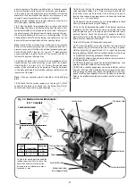
(a) Conventional Flue Appliance (CF/LLD)
1.
Remove the electrical lead plug by depressing the two locking
ears and pulling the plug downwards.
2.
Remove the burner from the boiler by slackening the two M6
retaining screws located in the burner housing ring and pulling the
burner clear. This will require the use of a 5mm allen key.
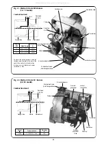
(b) Room Sealed Balance Flue Appliance (RS).
1.
Remove the burner box cover by pulling forwards to release the
ball studs. This will be found easier by pulling on the side of the han-
dle first to release two of the ball studs and then repeating on the
other side. Take care not to pivot the remaining two ball studs too far
around as this will cause damage to the spring clips.
2.
Remove the electrical lead plug by depressing the two locking
ears and pulling the plug.
3.
Push the electrical lead grommet back through the burner sur-
round box and feed the lead through the hole.
4.
Remove the burner from the boiler by slackening the two M6
retaining screws located in the burner housing ring and pulling the
burner clear. This will require the use of a 5mm allen key.
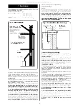
11.3 Flue system installation.
Install the appliance flue system as described in Section 7.
11.4 Heating system installation.
Before the appliance is fitted to the heating system
flush the system and mains water supply.
1.
Plumb the boiler into the central heating system.
2.
Check that all unused sockets have been plugged.
3.
Fill the system and vent all radiators and high points to remove
air from the system.
4.
Check the boiler and all pipework connections for leaks.
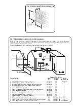
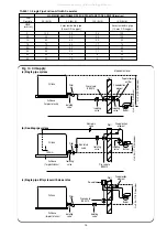
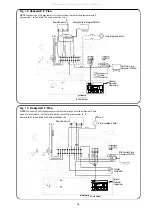
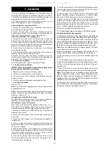
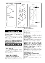
11.5 Oil supply installation.
(See Figs. 9 to 11).
NOTE:
Never route the oil supply pipe/hose directly below the com-
bustion chamber base.
NOTE:
Connection of rigid copper pipe to the oil pump is not recom-
mended. Connection to the oil pump should be made with flexible
oil hoses as shown in Fig. 11.
(a) Single pipe suction lift with de-aerator.
For connection of single pipe suction lift with de-aerator follow the
proceedure as for a double pipe system as described below.
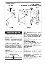
(b) Double pipe system oil return pipe.
When fitting an RS balanced flue appliance follow steps 1 to 11.
When fitting a CF/LLD appliance follow step 1 and fit a bulkhead fit-
ting to the bracket for the return pipe and continue from step 10.
1.
Remove the isolating valve bulkhead fitting by unscrewing the
locknut on the underside.
2.
Remove the blind grommet from the fixed burner surround box
and discard.
3.
Replace the blind grommet with the open grommet supplied in
the plastic bag.
4.
Slacken the pipe retaining clip screw located directly below the
grommet hole. When using 12mm copper pipe replace the clip with
the larger one supplied.
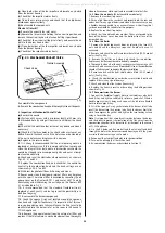
5.
Bend a piece of 10mm or 12mm copper tube ( as selected ) to the
correct profile to allow the pipe to be fed down the side of the appli-
ance. Make a slight chamfer on the end of the pipe to be fed
through the grommet to facilitate easy insertion.
6.
Lubricate the grommet hole with vaseline (or butter etc.) and
slide the pipe through the hole, supporting the grommet on its
underside to prevent it dislodging.
7.
Feed the pipe through the retaining clip, allowing approximately
80 mm of pipe to project beyond the clip, and tighten the retaining
screw. Take care not to overtighten the screw!
8.
Hold the pipe at the retaining clip and gently pull the pipe
forward sufficiently to allow a compression to 1/4 inch BSP female
fitting to be fitted for connection to the oil return flexible hose.
9.
Connect the fitting to the pipe and fit a 1/4 inch BSP taper thread
flexible hose, ensuring a good seal using PTFE tape or suitable oil
sealing compound. The flexible hose should have a 1/4 inch BSP
rotating union taper fitting at the other end with a 90 degree bend
and 1/4 inch BSP nipple for connection to the oil pump.
10.
Replace the isolating valve bulkhead fitting.
11.
Fit the oil supply pipe as described in the following section.
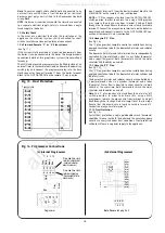
(c) Single pipe system oil supply pipe.
1.
Bend a piece of 10mm or 12mm copper tube (as selected) to the
correct profile to allow the pipe to be fed down the side of the appli-
ance. The pipe may be routed along either the right or left hand
side of the boiler as required. When using 12mm pipe fit a 12mm
to 10mm compression coupling and connect to the valve with a
short piece of 10 mm pipe, otherwise connect direct to the valve.
Note:
never use soldered joints on oil supply pipes as this could
cause a hazard in the case of a fire.
2.
Route the pipe back to the oil supply tank ensuring that it is
hard against the boiler, to allow installation of the side panel.
3.
With the isolating valve in the correct orientation tighten the
back-nut.
4.
Turn the isolating cock fully clockwise to close the valve.
5.
Open the main oil supply valve at the tank and check for any leaks.
6.
Place a suitable container below the bulkhead fitting and
open the valve.
7.
Draw off at least 2.5 litres of oil until a steady flow of clear
uncontaminated oil can be seen and turn off the isolating valve.
Note:
This method may not be possible on some installations
where a sub-gravity system is used. Where this problem arises
bleed the system using the oil pump as described in Section 12
and remove and clean the oil pump filter to remove any debris
collected as a result of installation.
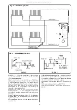
11.6
Replace the electrical control panel and side panels in
reverse order to the removal procedure of Section 5 and connect
the electrical supply as described in Section 10.
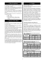
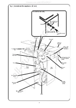
11. Installation
19
All manuals and user guides at all-guides.com