


14
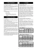
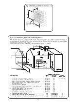
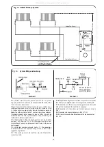
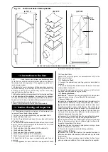
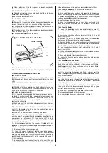
Fig. 12. Sealed Primary System.
Heating Flow (22 mm)
Heating Return (22 mm)
Automatic by-pass valve
to be fitted when thermostatic
valves are fitted on all radiators
Pressure
Relief
Valve
Expansion
Vessel
Pump
Static Head of System
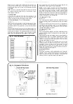
9.14
With an initial system pressure of 0.5 bar, a system
capacity of about 150 litres can be accommodated. Refer to BS
7074:1 for more information.
Where the system volume exceeds the value given in Table 11 an
additional expansion vessel, of suitable volume, should be fitted
to the heating return pipe-work as close to the boiler as possible.
Note:
The values given in Table 11 are the total system volumes.
The boiler primary water capacity given in Table 1 should be
deducted from the total system volume when calculating the
volume for radiators, pipe-work, etc.
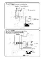
9.15
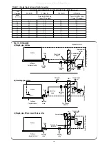
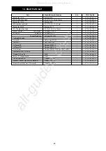
The method of filling the heating system can be by either
method 1 or 2 shown in Fig. 13. The filling point must be at low
level and must never be a permanent direct fixing to the mains
water supply.
9.16
Water loss must be replaced . See Fig. 13. The connection
should be made to the central heating return as close to the
appliance as possible.
9.17
The make up vessel, where fitted, must be fitted with a
non-return valve.
9.18
Repeated venting loses water from the system. It is essential
that this water is replaced and the system pressure maintained.
9.19
Connections to the mains water supply must not be made
without the authority of the local water company.
9.20
Connections to the system must resist a pressure of up to
3 bar.
9.21
Radiator valves must conform to BS 2767(10).
9.22
Other valves used should conform to the requirements of
BS 1010.
Heating return
Non return
valve
Non return
valve
Hose union
Test cock
Temporary hose
Stop cock
Auto
air vent
Heating return
Stop
cock
Fill point
Non return
valve
Make up
vessel
300 mm (12 in) min.
above the highest
point of the system.
Fig. 13. System filling and make-up.
Method 1
Method 2
All manuals and user guides at all-guides.com