


13
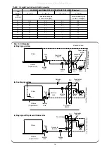
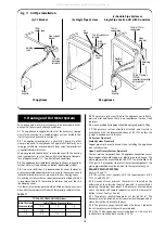
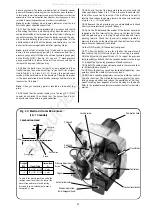
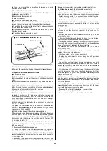
Fig. 11. Oil Pipe Installation.
(b) Single Pipe System.
RS Appliance
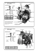
(a) CF Bracket.
CF Appliance
(c) Double Pipe System or
Single Pipe Suction Lift with De-aerator.
Burner
oil pump
Flexible
oil hose
Open
grommet
Turn fully clockwise
to isolate
Blind
grommet
Air
bleed
Burner
oil pump
10mm or 12mm
copper pipe
1/4" BSP female x
10/12mm
compression coupling
(not supplied)
10mm
copper pipe
10mm
copper pipe
Retaining
clip
Isolating
valve
Isolating
valve
Pipe support
bracket
Turn fully
clockwise
to isolate
The heating and hot water system must be provided in accor-
dance with the current Building Regulations.
9.1
The appliance is supplied with all of the necessary compo-
nents for connection to a sealed primary system. Suitable con-
trol systems are discussed in Section 10.
9.2
The appliance incorporates a circulating pump. No other
pump is required. The appliance will operate satisfactorily on a
two pipe small bore or micro bore system using thermostatical-
ly controlled radiator valves.
The pump speed should be set in accordance with the heating
load requirements to give a flow and return differential tempera-
ture of approximately 11° C under full load conditions.
9.3
The appliance is suitable for connection to all conventional indi-
rect hot water systems utilising an indirect double feed cylinder.
9.4
On new installations it is recommended a room thermostat
or programmable room thermostat is used in the main zone and
thermostatic radiator valves are used in further heating zones.
On existing systems where a room thermostat is already fitted it
is recommended to fit thermostatic radiator valves at least in
the sleeping zones.
A automatic system bypass should be fitted on heating systems
when all of the radiators are fitted with thermostatic radiator valves.
9.5
The pressure jet burner fitted to the appliance has full auto-
matic control and hence there is no requirement for heat leak
radiators.
9.6
Any unused boiler tappings should be plugged prior to filling.
9.7
The primary system should be flushed and treated in
accordance with the recommendations of BS 7593 before the
system is handed over to the user.
9.8 System Pipework
Sealed System Pipework
Copper pipe work must be used when installing the appliance
on a sealed system.
Open Vent Primary System Pipework
The first metre of pipework from all appliance connections must
be in copper; afterwards copper or plastic pipe can be used. The
plastic pipe must be manufactured to BS 7291 and installed to BS
5955 part 8. It is important to protect the system components; the
plastic pipe specified must be resistant to the ingress of oxygen.
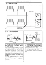
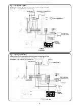
SEALED PRIMARY SYSTEM
See Figs 12 and 13.
9.9
The system must comply with the requirements of BS
7074:1 and BS 5449:1.
9.10
A manual reset overheat thermostat is located on the
underside of the electrical control box and is accessible by
removing the cabinet front panel. If a boiler over-heat condition
arises the boiler will remain inoperative until the thermostat
button is reset. See Figs. 2 and 3.
9.11
The pressure relief valve operates at 3 bar (45 lb./in
2
). The
discharge must be directed away from electrical components or
where it might be a hazard to the user.
9.12
The pressure gauge, located above the burner, indicates
the system pressure which must be maintained.
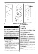
9.13
The 10 litre expansion vessel is charged to 0.5 bar and is
suitable for a static head of 5 metres (17.5 ft).
9. Heating and Hot Water System
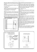
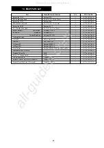
Table 11.
TOTAL SYSTEM VOLUME (Litres)
Initial System
Initial Charge Pressure (bar)
Pressure (bar)
0.5
1.0
1.5
0.5
150
–
–
1.0
90
115
–
All manuals and user guides at all-guides.com