DHW heating
|
47
6 720 807 794 (2013/04)
UNIMAT
8
DHW heating
8.1
Systems for DHW heating
The UNIMAT UT-L boilers can be used for central DHW
heating. They can be combined with any Bosch DHW
cylinder. The WST cylinders are available as horizontal or
vertical versions in different sizes with up to 6000 l
capacity. Subject to application, they are equipped with
an internal indirect coil or external heat exchanger.
The DHW cylinders can be used singly or in combination
with other cylinders. With the primary store system,
different cylinder sizes and different heat exchanger sets
can be combined. This means system solutions are
available for any demand and many applications.
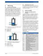
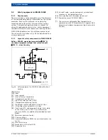
Fig. 29 DHW heating according to the cylinder principle
with an internal indirect coil
AW Hot water outlet
EK
Cold water inlet
RS
Cylinder return
VS
Cylinder flow
Fig. 30 DHW heating according to the primary store
principle with an external heat exchanger
AW Hot water outlet
EK
Cold water inlet
RH
Fuel return (to boiler)
VH
Fuel flow (from boiler)
8.2
DHW temperature control
The DHW temperature is adjusted and controlled by the
CFB control system for DHW heating. Both versions are
matched to the heating circuit control unit and offer
many application options.
9
System examples
9.1
Information regarding all system
examples
The system examples in this chapter show options for
the hydraulic connection of the UNIMAT UT-L boilers. In
addition, the examples show important control and
electrical connections for the relevant application.
Detailed information regarding the number, controls,
equipment level and design of further heating circuits, as
well as the installation of DHW cylinders and other
consumers, can be found in the relevant technical
guides.
Information regarding further options for system layout
and engineering aids are available from Bosch technical
consultants. Specialists at your local sales office can
create a control panel layout tailored to your needs. In
this way, Bosch offers an entire matching concept right
through to commissioning the heating system.
The diagrams and associated design information for the
system examples with the UNIMAT UT-L boilers offer
non-binding information regarding a possible hydraulic
connection. No claim is made as to their completeness.
Each system example is a non-binding recommendation
for a certain version of the heating system. Practical
implementation is subject to currently applicable
technical rules.
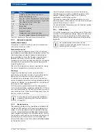
List of abbreviations
EK
RS
VS
AW
6 720 640 417-11.1il
EK
RH
VH
AW
6 720 640 417-12.1il
Abbr.
Meaning
BR / BRII
Burner (stage I / stage II)
DDC
Direct Digital Control (overriding control
unit)
GLT
Building management control (overriding
control unit)
FK
Boiler water temperature sensor
FR
Return temperature sensor
FRS
Strategy return temperature sensor
FV
Flow temperature sensor
FVS
Strategy flow temperature sensor
FZ
Additional sensor for the return
temperature
HK
Heating circuit
HB
High temperature heating circuit
KR
Flow-check valve
LT
Low temperature heating circuit
PH
Heating pump
PK
Boiler circuit pump
PWT
Heat exchanger pump
RK
Boiler return
Table 26 Summary of frequently used abbreviations
Содержание UT-L 1
Страница 1: ...Technical guide Heating boiler UNIMAT UT L 6 720 807 794 2013 04 EN ...
Страница 86: ...86 UNIMAT 6 720 807 794 2013 04 Notes ...
Страница 87: ... 87 6 720 807 794 2013 04 UNIMAT ...

