background image

34

 | 

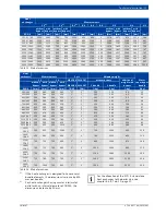
Burner


UNIMAT

6 720 807 794 (2013/04)

UT-L 

46 

9300 

4911 

4500 

16 

1260 

UT-L 

48 

10000 

5658 

5200 

16 

1446 

UT-L 

50 

11200 

5360 

4930 

16 

1336 

UT-L 

52 

12000 

6396 

5900 

13 

1550 

16 

1470/1570 

UT-L 

54 

12600 

5658 

5200 

16 

1446 

UT-L 

56 

14000 

6825 

6300 

13 

1600 

16 

1530/1630 

UT-L 

58 

14700 

6396 

5900 

13 

1550 

16 

1470/1570 

UT-L 

60 

16400 

6825 

6300 

13 

1600 

16 

1530/1630 

UT-L 

62 

17500 

7263 

6700 

13 

1750 

16 

1620/1770 

UT-L 

64 

19200 

7263 

6700 

13 

1750 

16 

1620/1770 

UNIMAT

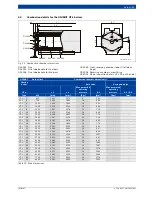
Burner attachment limit

Heating 

boiler

Maximum permissible 

torque for the burner 

fixing equipment

L 3

L 4

L 5

B 1

H 1

H 2

Type

[Nm]

[mm]

[mm]

[mm]

[mm]

[mm]

[°]

UT-L 

2200 

535 

190 

225 

1050 

725 

460 

UT-L 

2200 

625 

260 

190 

1200 

800 

560 

UT-L 

2200 

625 

260 

190 

1200 

800 

560 

UT-L 

2200 

685 

290 

190 

1300 

850 

620 

UT-L 

2200 

745 

325 

190 

1400 

900 

685 

UT-L 

10 

2200 

685 

290 

190 

1300 

850 

620 

UT-L 

12 

2200 

775 

350 

190 

1450 

925 

720 

UT-L 

14 

2400 

745 

325 

190 

1400 

900 

685 

UT-L 

16 

2400 

835 

385 

190 

1550 

975 

785 

UT-L 

18 

3600 

775 

350 

190 

1450 

925 

720 

UT-L 

20 

3600 

860 

412 

190 

1600 

1000 

815 

UT-L 

22 

3600 

900 

430 

257 

1700 

1050 

795 

UT-L 

24 

3800 

835 

385 

190 

1550 

975 

785 

UT-L 

26 

3800 

960 

470 

257 

1800 

1100 

855 

UT-L 

28 

5500 

860 

412 

190 

1600 

1000 

815 

UT-L 

30 

6000 

900 

430 

257 

1700 

1050 

795 

UT-L 

32 

6000 

1075 

510 

257 

2000 

1200 

975 

UT-L 

34 

8200 

960 

470 

257 

1800 

1100 

855 

UT-L 

36 

8200 

1165 

560 

257 

2150 

1275 

1065 

UT-L 

38 

8200 

1250 

600 

257 

2300 

1350 

1150 

UT-L 

40 

16500 

1075 

510 

257 

2000 

1200 

975 

UT-L 

42 

16500 

1165 

560 

257 

2150 

1275 

1065 

UT-L 

44 

16500 

1340 

640 

259 

2450 

1425 

1250 

UT-L 

46 

16500 

1250 

600 

257 

2300 

1350 

1150 

UT-L 

48 

17500 

1425 

695 

259 

2600 

1500 

1330 

UT-L 

50 

17500 

1340 

640 

259 

2450 

1425 

1250 

UT-L 

52 

17500 

1540 

735 

259 

2800 

1600 

1450 

UT-L 

54 

17500 

1425 

695 

259 

2600 

1500 

1330 

UT-L 

56 

17500 

1715 

775 

294 

3100 

1750 

1630 

UT-L 

58 

17500 

1540 

735 

259 

2800 

1600 

1450 

UT-L 

60 

17500 

1715 

775 

294 

3100 

1750 

1630 

UT-L 

62 

17500 

1830 

825 

294 

3300 

1850 

1745 

UT-L 

64 

17500 

1830 

825 

294 

3300 

1850 

1745 

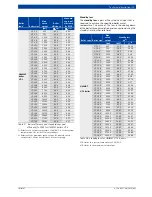
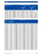
Table 21 Main dimensions

UNIMAT

Output limit

Combustion chamber dimension(s)

Heating 

boiler

Bare tube

Corrugated pipe

UT-L

L 1

L 2

Max. permitted 

operating 

pressure

D 1

Max. permitted 

operating 

pressure

D 2 / D 1

Type

kW

[mm]

[mm]

[bar]

[mm]

[bar]

[mm]

Table 20 Main dimensions

Содержание UT-L 1

Страница 1: ...Technical guide Heating boiler UNIMAT UT L 6 720 807 794 2013 04 EN ...

Страница 2: ...ncy to DIN and standby loss 28 3 5 5 Flue gas temperature 30 4 Burner 32 4 1 General requirements 32 4 2 Information on burner selection 32 4 3 Matched pressure jet burners 32 4 4 Combustion details for the UNIMAT UT L boilers 33 5 Regulations and operating conditions 35 5 1 Extracts from the regulations 35 5 2 German Immissions Act BImSchG 36 5 2 1 Table extracted from the 1st BImSchV Small and m...

Страница 3: ...s 66 10 1 2 Handling dimensions 66 10 2 Design of installation rooms and combustion air supply 67 10 2 1 Installation location 67 10 2 2 Combustion air supply 67 10 3 Installation dimensions 69 10 3 1 Installation room dimensions for the UNIMAT UT L boilers 69 10 3 2 Installation room dimensions for the UNIMAT UT L boilers with flue gas heat exchanger 70 10 4 Additional safety equipment to DIN EN ...

Страница 4: ... of these boilers This means they have a low weight and require only a small floor area for installation The burner door can close on the right hand or left hand side Environmentally responsible with low emissions The 3 pass design and water cooled combustion chamber offer ideal conditions for operation with low emissions especially in conjunction with the advanced burners that are matched to the ...

Страница 5: ...mparing the energy utilisation of conventional boilers and condensing boilers or boilers with condensing heat exchangers an energy statement such as the example shown in Fig 3 can result Condensation heat latent heat The proportion of condensation heat in natural gas is approx 11 relative to the net calorific value Hi With low sulphur fuel oil the proportion of condensation heat is approx 7 relati...

Страница 6: ...e condensing heat exchanger ECO 6 connected separately to a low temperature heating circuit Fig 4 Condensation heat utilisation at 40 30 C example with natural gas A Proportion of operation with condensation heat utilisation a Annual heat load curve b Dew point temperature curve example with natural gas c System temperatures ϑA Outside temperature ϑHW Heating water temperature WHa Annual heat load...

Страница 7: ... return temperature raising e g 4 way mixers bypass circuits low loss headers depressurised distributors etc For more detailed information on the hydraulic connection see chapter 9 on page 47 ff 2 3 Economic viability considerations 2 3 1 Simplified comparison of conventional boilers and condensing boilers or boilers with condensing heat exchangers Fuel costs Given Building heat demand QN 2000 kW ...

Страница 8: ...r design of the boiler and additional equipment enables universal application Round boiler casing made of textured aluminium sheeting Visible parts of the boiler primed in anthracite grey and red Thermal insulation 100 mm and extremely well insulated burner door Boiler pressure body with connections for flow return safety valve and drain As an option with inspection port on the water side Bottom r...

Страница 9: ...er is built using the 3 pass design and the countercurrent heat exchanger principle Together with an effective heating surface design these are the prerequisites for low emissions and high energy efficiency Subject to the system the UNIMAT UT L boilers achieve very high standard seasonal efficiency to DIN which can be increased to up to 106 with the boiler with condensing heat exchanger Fig 6 Sect...

Страница 10: ...construction This means the most suitably sized heat exchanger or number thereof for the project in question can be chosen on an individual basis Fig 7 Function principle of the UNIMAT UT L boiler with flue gas heat exchanger 1 Burner door 2 Safety valve connector Fig 51 page 73 3 Water guide system 4 Return Fig 50 page 72 and Fig 53 page 76 5 High grade insulation without thermal bridges 6 Flow F...

Страница 11: ...even higher efficiency can be achieved If the flue gas heat exchanger is operated with fuel oil not low sulphur quality ensure a corresponding minimum water inlet temperature at the flue gas heat exchanger of 60 C to protect it from corrosion on the flue gas side With oil operation an optional control on the water side can be used to raise the water inlet temperature at the flue gas heat exchanger...

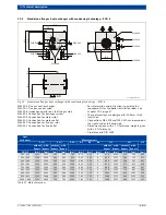
Страница 12: ...295 2040 1174 2152 1540 1460 1055 1750 710 120 1055 UT L 2 750 3516 2680 2425 1324 2302 1695 1610 1180 2100 910 120 1180 UT L 4 1000 3516 2680 2425 1324 2302 1695 1610 1180 2100 910 120 1180 UT L 6 1000 3786 2950 2695 1424 2402 1795 1710 1240 2350 910 120 1240 UT L 8 1250 4056 3220 2960 1524 2502 1895 1810 1340 2560 930 160 1340 UT L 10 1350 3778 2950 2695 1424 2402 1795 1710 1240 2350 910 120 124...

Страница 13: ...00 4650 1610 240 2000 UT L 484 10000 8285 6315 5990 2724 3912 3010 2200 5320 1890 280 2200 UT L 504 11200 8121 5980 5655 2574 3947 2875 2100 5050 1630 280 2100 UT L 524 12000 9086 7050 6725 2924 4297 3239 2440 6000 1890 280 2440 UT L 544 12600 7162 6315 5990 2724 4097 3010 2200 5320 1890 280 2200 UT L 564 14000 8803 7530 7170 3224 4597 3542 2600 6390 2100 320 2600 UT L 584 14700 9086 7050 6725 292...

Страница 14: ...0 mm 740 1 2 560 W32 509 W32 000 D03 000 W32 510 H 2 H 1 B 1 B 2 W32 008 6 720 803 977 10 1itl Heat exchanger Shipping weight Water capacity Measurements 1 bundle 2 bundle B 12 B 2 H 2 ECO 7 kg kg l mm mm mm 390 245 90 140 10 809 490 459 510 325 110 180 15 929 550 539 600 378 140 220 20 1019 595 592 690 432 160 260 26 1109 640 646 750 485 190 310 29 1169 670 699 890 592 230 370 37 1309 740 806 930...

Страница 15: ...18 UT L 20 ECO 7 heat exchanger 510 325 510 325 510 325 510 325 600 378 600 378 600 378 690 432 690 432 750 485 750 485 390 245 510 325 600 378 690 432 600 378 UNIMAT UT L UT L 22 UT L 24 UT L 26 UT L 28 UT L 30 UT L 32 UT L 34 UT L 36 UT L 38 UT L 40 UT L 42 ECO 7 heat exchanger 890 592 890 592 930 618 930 618 1000 672 1000 672 1110 752 1110 752 1300 885 1300 885 1350 985 750 485 890 592 930 618 ...

Страница 16: ...2 000 W32 507 D03 000 W32 510 H 2 H 1 B 1 B 2 W32 008 6 720 803 977 12 1itl Heat exchanger Shipping weight Measurements Port 1 bundle 2 bundle Water capacity B 1 B 22 H 2 W32 506 ECO 6 kg kg mm mm mm mm DN 390 260 90 140 10 794 475 474 1 510 335 110 180 15 914 535 549 1 600 385 140 220 20 1004 580 599 1 690 460 170 260 26 1094 625 674 1 750 485 190 310 29 1154 655 699 1 850 560 230 360 37 1254 705...

Страница 17: ...eat exchanger 510 335 510 335 600 385 600 385 690 460 690 460 690 460 750 485 750 485 850 560 890 610 390 260 510 335 510 335 600 385 600 385 690 460 750 485 850 560 510 335 600 385 690 460 UNIMAT UT L UT L 22 UT L 24 UT L 26 UT L 28 UT L 30 UT L 32 UT L 34 UT L 36 UT L 38 UT L 40 UT L 42 ECO 6 heat exchanger 890 610 890 610 930 635 930 635 1000 685 1000 685 1110 760 1110 760 1300 885 1300 885 135...

Страница 18: ...ternal diameter of DN150 the dimensions increase by 50 mm B 1 B 4 B 2 L 1 L 2 200 L 3 80 L 4 80 H 3 H 4 H 5 W32 509 W32 000 W32 002 W32 008 W32 510 H 2 H 1 W32 540 W32 506 B 3 W32 541 0 90 0 90 6 720 803 977 13 1itl Heat exchanger Measurements L 11 L 21 B 12 B 2 B 3 B 4 H 1 H 2 H 3 without bypass with bypass without bypass with bypass without bypass with bypass without bypass with bypass ECO 7 mm ...

Страница 19: ... 2167 947 Heat exchanger Measurements Port Shipping weight Water capacity per bundle L 3 L4 additional weight with bypass W32 506 1 bundle 2 bundle ECO 7 mm mm mm DN kg kg kg l 390 245 353 380 353 285 1 100 150 20 10 510 325 353 380 353 360 1 130 200 40 15 600 378 353 380 353 410 1 160 240 60 20 690 432 353 380 353 485 1 190 290 80 26 750 485 353 380 353 510 1 220 340 100 29 890 592 353 418 353 63...

Страница 20: ...th 3 tolerance Pipe thread to DIN 2999 B 1 B 4 B 2 L 1 L 2 200 200 L 3 80 L 4 80 H 3 W32 509 W32 000 W32 002 W32 008 W32 510 H 2 H 1 W32 506 W32 540 B 3 W32 507 W32 541 0 90 0 90 6 720 803 977 14 1itl Heat exchanger Measurements L 11 L 21 B 12 B 2 B 3 B 4 H 1 H 2 H 3 without bypass with bypass without bypass with bypass without bypass with bypass without bypass with bypass ECO 6 mm mm mm mm mm mm ...

Страница 21: ...s with bypass without bypass with bypass W32 506 W32 507 1 bundle 2 bundle ECO 6 mm mm mm mm DN DN kg kg kg kg 390 260 353 380 353 285 1 1 100 150 20 10 510 335 353 380 353 360 1 1 130 200 40 15 600 385 353 380 353 410 1 1 160 240 60 20 690 460 353 380 353 485 1 1 190 290 80 26 750 485 353 380 353 510 1 1 220 340 100 29 850 560 353 530 353 585 1 1 260 400 140 37 890 610 353 418 353 635 1 1 290 440...

Страница 22: ...44 2938 4592 DN125 1722 2479 2296 3306 3444 4959 4592 6612 DN150 2479 4408 3306 5877 4959 8816 6612 11755 DN200 4408 6887 5877 9183 8816 13775 11755 18367 DN250 6887 9918 9183 13224 13775 19200 18367 19200 DN300 9918 13500 13224 18000 DN350 13500 17633 18000 19200 DN400 Table 15 Internal diameters of flow and return connections subject to design spread and rated output Rated output1 1 Actual outpu...

Страница 23: ...ead R 120 mm long with DN 32 150 connectors Female connections with cylindrical female thread R 60 mm long with DN 200 400 connectors N2 Female connections with cylindrical female thread R 60 mm long with DN 65 80 connectors Female connections with cylindrical female thread R 75 mm long with DN 32 50 connectors Female connections with cylindrical female thread R 40 mm long with DN 100 400 connecto...

Страница 24: ...nectors and the flow rate The graph in Fig 14 shows the pressure loss on the water side for the UNIMAT UT L boilers Fig 14 Pressure loss on the water side for UNIMAT UT L boilers for internal diameters of flow and return connections page 22 ΔpH pressure loss on the heating water side VH Flow rate 200 100 40 50 20 30 10 5 10 100 50 1000 500 VH m3 h ΔpH mbar 6 720 642 347 14 1il D N 4 0 D N 6 5 D N ...

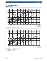
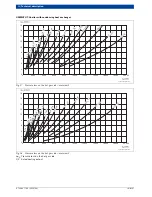
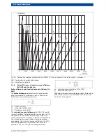
Страница 25: ...2 0 0 2000 4000 6000 8000 10000 12000 14000 16000 18000 20000 U T L 4 U T L 1 U T L 1 0 U T L 1 4 U T L 1 8 U T L 2 4 U T L 2 8 U T L 3 0 U T L 3 4 U T L 4 0 U T L 4 2 U T L 4 6 U T L 5 0 U T L 5 4 U T L 5 8 UT L 60 UT L 64 QK kW 6 720 803 977 02 1ITL 18 16 14 12 10 8 6 4 2 0 0 2000 4000 6000 8000 10000 12000 14000 16000 18000 20000 UT L 2 UT L 6 UT L 8 U T L 1 2 U T L 2 0 U T L 1 6 U T L 2 2 U T ...

Страница 26: ... 2 0 0 2000 4000 6000 8000 10000 12000 14000 16000 18000 20000 U T L 4 U T L 1 0 U T L 1 4 U T L 18 U T L 2 4 U T L 2 8 U T L 3 0 U T L 3 4 U T L 4 0 U T L 4 2 U T L 4 6 U T L 5 0 U T L 5 4 U T L 5 8 UT L 60 UT L 64 6 720 803 977 04 1ITL 18 16 14 12 10 8 6 4 2 0 0 2000 4000 6000 8000 10000 12000 14000 16000 18000 20000 UT L 2 UT L 6 U T L 8 U T L 1 6 U T L 1 2 U T L 2 0 U T L 3 2 U T L 3 6 U T L 3...

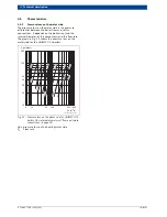
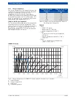
Страница 27: ...volume load can be selected for the UNIMAT UT L boilers UNIMAT UT L boiler Fig 19 Combustion chamber volume load for UNIMAT UT L boiler subject to the boiler output overview 1 FVB Combustion chamber volume load QB Rated heating output 2 0 1 9 1 7 1 5 1 3 1 1 0 2000 4000 6000 8000 10000 14000 16000 12000 18000 20000 UT L 4 UT L 10 UT L 14 U T L 18 U T L 2 4 U T L 2 8 U T L 3 0 U T L 3 4 U T L 4 0 U...

Страница 28: ...l load efficiency levels at five fixed points in the relative boiler output ratings The values measured for efficiency at partial load subject to the relative boiler output ratings should be entered accordingly The standard seasonal efficiency to DIN for heating operation is calculated from the values derived in this way using the following equation ηN Standard seasonal efficiency to DIN ϕi Relati...

Страница 29: ... 44 8000 92 8 95 6 UT L 46 9300 92 2 95 4 UT L 48 10000 93 1 95 8 UT L 50 11200 92 2 95 4 UT L 52 12000 92 6 95 6 UT L 54 12600 92 7 95 6 UT L 56 14000 93 5 96 0 UT L 58 14700 92 2 95 4 UT L 60 16400 93 4 96 0 UT L 62 17500 92 9 95 7 UT L 64 19200 92 8 95 7 Table 17 Boiler efficiency and standard seasonal efficiency to DIN for UNIMAT boilers UT L Boiler type Boiler size Max rated output Standby lo...

Страница 30: ... to other temperature pairs Tab 19 Example Given UNIMAT UT L boiler Rated output QK 6000 kW System temperatures 100 80 C Check Change of 15 K in the flue gas temperature Tab 19 Flue gas temperature read off ϑA 198 C Fig 21 Result Flue gas temperature at full boiler load 198 C 15 K 213 C UNIMAT UT L boiler Fig 21 Flue gas temperatures for UNIMAT UT L boilers subject to the boiler load overview 1 ηK...

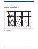
Страница 31: ...ing heat exchanger averages for the series a Water inlet temperature into the condensing heat exchanger of 60 C b Water inlet temperature into the condensing heat exchanger of 30 C ϑA Flue gas temperature ϕK Boiler load 220 210 200 190 180 170 160 150 0 2000 4000 6000 8000 10000 12000 14000 16000 18000 20000 91 1 91 5 92 0 92 4 92 9 93 3 93 7 94 1 UT L 2 U T L 12 U T L 1 6 U T L 2 0 U T L 2 2 U T ...

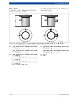
Страница 32: ...he factory Fill the gap between the door lining and blast tube with fireproof flexible material The burner door must be able to be opened and pivoted out unimpeded In the case of oil combustion size the oil hoses and cables accordingly In the case of gas combustion provide a gas line compensator in the longitudinal direction of the boiler With this the gas train can be separated at this point when...

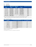
Страница 33: ...ing pressure D 1 Max permitted operating pressure D 2 D 1 Type kW mm mm bar mm bar mm UT L 1 650 1821 1570 6 534 UT L 2 750 2200 1930 16 600 UT L 4 1000 2200 1930 16 600 UT L 6 1000 2470 2180 16 660 UT L 8 1250 2667 2378 16 726 UT L 10 1350 2470 2180 16 660 UT L 12 1500 3148 2850 16 776 UT L 14 1900 2667 2378 16 726 UT L 16 2000 3195 2878 16 842 UT L 18 2500 3148 2850 16 776 UT L 20 2500 3552 3235...

Страница 34: ...412 190 1600 1000 815 UT L 22 3600 900 430 257 1700 1050 795 UT L 24 3800 835 385 190 1550 975 785 UT L 26 3800 960 470 257 1800 1100 855 UT L 28 5500 860 412 190 1600 1000 815 UT L 30 6000 900 430 257 1700 1050 795 UT L 32 6000 1075 510 257 2000 1200 975 UT L 34 8200 960 470 257 1800 1100 855 UT L 36 8200 1165 560 257 2150 1275 1065 UT L 38 8200 1250 600 257 2300 1350 1150 UT L 40 16500 1075 510 ...

Страница 35: ...ors Notification and permit obligations Subject to the Building Regulations of each country boiler systems may require notification to or approval from appropriate authorities Observe country specific requirements Service We recommend having the system serviced regularly and cleaned as required As part of this it should be checked that the entire system is working properly We recommend that system...

Страница 36: ...test available technology Efficiency at rated boiler output2 QK 400 kW 94 Flue losses 4 kW QFA 25 kW 25 kW QFA 50 kW QFA 50 kW 11 10 9 Repeat tests as per para 15 regarding soot value CO emissions flue loss Newer systems3 every 3 years older systems4 every 2 years 3 Systems that were commissioned or that underwent major modifications boiler replacement or fuel conversion 12 years ago or less 4 Sys...

Страница 37: ...ms we recommend postponing the test until it can be carried out without interruption Fuels The fuels to be burned must comply with the notice of approval and be available in the quality determined for the system Since the level of nitrogen in light fuel oil has a significant effect on the formation of NOx the nitrogen content of light fuel oil must be known in order to assess the NOx test levels T...

Страница 38: ... in from chemical cleaners or paint shops Prevention of corrosion damage Corrosion damage has occurred if the function of the heating system is impaired by corrosion This may become apparent through blockages boiling noises poor circulation rust perforations reduced output or the formation of cracks This usually only occurs if oxygen continually enters the heating water In order to prevent this de...

Страница 39: ...the outlet shut off valve via a tee on the inlet side and to the return between the boiler and return shut off device on the pressure side The additive can be topped up via the dosing station on the pressure side of the pump After this tightly seal all boiler valves to prevent the ingress of airborne oxygen during the idle time To ensure the preservative solution is thoroughly mixed in the water m...

Страница 40: ...bstances pH value at 25 C 8 10 8 10 5 8 5 10 5 Alkaline earths total hardness mmol l dH 0 02 0 1 0 02 0 1 0 02 0 1 Oxygen O2 mg l 0 1 0 1 0 1 Circulating water General requirements Colourless clear and free of undissolved substances pH value2 at 25 C 2 For operation with a low salt content adjust the pH value or the p value with trisodium phosphate For saline operation the alkalinity usually adjus...

Страница 41: ...n for performance of the water treatment will be checked Boiler type Steam output Average operating pressure Condensation rate Special features e g sterile steam existing treatment system other on site consumers etc 2 Details of untreated water analysis 2 1 Minimum details for designing a water softener unit Total hardness mmol l Electrical conductivity μS cm or dH Or salt content TDS mg l Or calc...

Страница 42: ...n of the noise development in the combustion chamber is transmitted along the flue system to the chimney This sound is emitted via the surface of the flue system as airborne noise and escapes at the chimney The noise from a boiler system predominantly contains low frequency sound These sound emissions can be effectively reduced with a flue gas silencer To design a flue gas silencer to maintain the...

Страница 43: ...ns By actuating a boiler circuit pump and an actuator 3 way mixer the CME 930 auxiliary module safeguards the required boiler operating conditions for boilers with a minimum return temperature In conjunction with the appropriate plumbing configuration compliance with the required boiler operating conditions is guaranteed When the boiler circuit is in automatic mode appropriate adjustments should b...

Страница 44: ...oiler systems Separate boiler curve can be adjusted with third party control of the consumers Control of a boiler circuit pump for systems with depressurised headers or low loss headers Output dependent control of a boiler circuit pump via a 0 10 V signal in conjunction with modulating burners Application of a potential free signal for an external fault display or for switching between gas and oil...

Страница 45: ...lowing options are possible for controlling the minimum return temperature Overriding control of the heating circuit actuators The heating circuit actuators are closed if the minimum return temperature is not reached independent of the heat demand of the heating circuits For this setting all heating circuits must be fitted with an actuator and controlled by the CFB control unit Control of a separa...

Страница 46: ...the boiler They can be used instead of the CFB 810 control unit Fig 28 UNIMATIC display units and control units for UT L boilers dimensions in mm Available Not available 7 5 BCO boiler control The intuitive BCO boiler control based on a PLC offers maximum operating data transparency for optimum boiler operation and also provides comprehensive control solutions for medium and large scale systems Th...

Страница 47: ...onnections for the relevant application Detailed information regarding the number controls equipment level and design of further heating circuits as well as the installation of DHW cylinders and other consumers can be found in the relevant technical guides Information regarding further options for system layout and engineering aids are available from Bosch technical consultants Specialists at your...

Страница 48: ...sated mode It is also possible to control individual heating circuits in room temperature dependent mode with a room temperature sensor in a reference room For this the actuators and heating circuit pumps are constantly actuated by the CFB control unit The number and version of heating circuits that can be controlled depend on the boiler control The CFB control unit can also actuate the burners wh...

Страница 49: ...ot water flow line 11 001 Hot water return line 13 003 Shut off valve In temperature maintaining mode the shut off valve D10 008 in the hot water flow is open and the 3 way control valve D11 006 in the hot water return is closed In boiler mode the temperature maintaining pump D13 007 is stopped and the shut off valve on the inlet side D13 010 is closed A B AB flow direction marking indicated on th...

Страница 50: ...off valve 10 001 Hot water flow line 11 001 Hot water return line 13 003 Shut off valve In temperature maintaining mode the shut off valve D10 008 in the hot water flow is open and the 3 way control valve D11 006 in the hot water return is closed In boiler mode the temperature maintaining pump D13 007 is stopped and the shut off valve on the inlet side D13 010 is closed M M M M M M M M 13 003 6 I ...

Страница 51: ...Temperature maintenance Can be used up to boiler output limit Motorised output of temperature maintaining pump Nominal diameter Measure ments Shipping weight D13 0071 1 Pipe thread to DIN 2999 D13 0101 D13 0111 D13 0121 D13 0132 2 Internal diameter for flanges to DIN 2633 DIN 2634 and DIN 2635 L1 Type kW kW DN DN DN DN DN mm kg HD 1 1000 0 06 40 20 20 20 25 20 579 8 HD 2 5200 0 07 40 25 25 25 32 2...

Страница 52: ...EN 12828 with direct heating RK Return VK Flow 1 Heat sources 2 Shut off valve flow return 3 Temperature control unit 4 High limit safety cut out STB 5 Temperature capturing facility 6 Diaphragm safety valve MSV 2 5 bar 3 0 bar 7 Lift spring safety valve HFS 2 5 bar 8 Flash trap ET not required if a high limit safety cut out with a limit 110 C and a maximum pressure limiter are additionally provid...

Страница 53: ... in the maximum achievable average operating flow temperatures according to table The boiler temperature must be at least 70 C It can be modulating or kept constant 9 3 Sizing and installation information 9 3 1 Boiler circuit pump in the bypass as shunt pump Fig 35 Sample hydraulic circuit for a 1 boiler system with boiler circuit pump in the bypass FR Return temperature sensor KR Flow check valve...

Страница 54: ...te of the heating circuits in l h Total boiler flow rate VKges The head of the boiler circuit pump is the result of The pressure loss of the boiler at the selected flow rate VPK The pressure loss in the pipework and All individual pressure loss levels in the boiler circuit path A C D B Fig 35 Due to the pump and system curves the total flow rate via the boiler cannot be calculated simply by adding...

Страница 55: ... of every boiler circuit pump should correspond to the flow rate of the heating circuit pumps For systems with gas condensing boilers there are special requirements to be followed e g maintaining as low a return temperature as possible The pump rate of the boiler circuit pump may then need to be matched to the pump rate of the heating circuits Sizing the 3 way valve Size the 3 way valve for the fl...

Страница 56: ...aulic balancing line is to function correctly To ensure good separation with the simultaneous function as a dirt separator size the line in such a way that there is virtually no pressure loss between the flow and return With the nominal water volume flow velocities of 0 1 m s to 0 2 m s can be expected This makes simultaneous usage as a dirt separator possible In order that the heating circuit flo...

Страница 57: ...s increases the boiler return temperature To raise the return temperature the heating circuit actuators are regulated with overriding control The flow rate to the boiler is restricted until the set value for return temperature control has been reached by mixing in flow water Once the set value for the return temperature has been reached heating circuit control is re enabled Special design informat...

Страница 58: ...rcuit using CFB control unit Function description The 3 way valve is actuated to control the return temperature The return temperature sensor measures the boiler return temperature If this falls below the set value the flow rate to the heating return is constantly restricted by actuating the 3 way valve If the return temperature rises above the set value the 3 way valve is reopened and the flow ra...

Страница 59: ... control the return temperature the 3 way valve is actuated as is the boiler circuit pump which is installed in the bypass line to the boiler The return temperature sensor measures the boiler return temperature If this falls below the set value the flow rate to the return is constantly restricted and the bypass from the heating return to the heating flow is opened The heating circuit flow rate rem...

Страница 60: ...ure controlled via a separate actuator in the boiler circuit and a boiler circuit pump as primary circuit pump 2 stage or modulating burner mode Control of heating circuit using CFB control unit or on site control unit Function description The 3 way valve is actuated to control the return temperature The return temperature sensor measures the boiler return temperature If this falls below the set v...

Страница 61: ...e control unit Function description The 3 way valve is actuated to control the return temperature The return temperature sensor measures the boiler return temperature If this falls below the set value the flow rate to the return is constantly restricted by actuating the 3 way valve If the return temperature rises above the set value the 3 way valve is reopened and the flow rate to the heating circ...

Страница 62: ...sor falls below the set value the flow rate to the boiler return is constantly restricted and the bypass from the heating return to the heating flow is opened The heating circuit flow rate remains almost constant even during this operating phase The boiler circuit pump safeguards the optimum flow rate in the boiler circuit Targeted utilisation of the condensing effect is possible with the ECO 6 co...

Страница 63: ... actuated to control the return temperature The return temperature sensor measures the boiler return temperature If this falls below the set value the flow rate to the heating return is constantly restricted by actuating the 3 way valve If the return temperature rises above the set value the 3 way valve is reopened and the flow rate to the heating circuit increases Targeted utilisation of the cond...

Страница 64: ...return is constantly restricted by actuating the 3 way valve If the return temperature rises above the set value the 3 way valve is reopened and the flow rate to the heating circuit increases Any boilers not in operation are hydraulically shut off Targeted utilisation of the condensing effect is possible with the condensing heat exchanger ECO 6 connected separately to the low temperature heating c...

Страница 65: ...t monitors the minimum return temperature which depends on the type of flue gas heat exchanger or on the fireplace If the temperature falls below the minimum return temperature of 60 C the mixer closes The cold return water cannot enter the ECO 6 or ECO 7 If the temperature in this circuit rises above 60 C the mixer enables the system return Special design information If the SRWT actuator is insta...

Страница 66: ...m handling dimensions Entrance UNIMAT UT L boiler UNIMAT UT L boiler UNIMAT UT L boiler with flue gas heat exchanger Boiler size Minimum width Minimum height Minimum width Minimum height mm mm mm mm UT L 1 1400 1850 1500 1865 UT L 4 UT L 2 1550 2000 1650 2015 UT L 10 UT L 6 1650 2100 1755 2115 UT L 14 UT L 8 1750 2200 1855 2215 UT L 18 UT L 12 1800 2250 1910 2265 UT L 24 UT L 16 1900 2350 1995 236...

Страница 67: ...ividual components Provide suitable lifting gear in the boiler installation room to move heavy equipment The internal height and width of all walk on surfaces must be sufficient Access to the system must be ensured in line with local regulations If the internal height of the installation room is lower than required for structural reasons determine the minimum height together with the local respons...

Страница 68: ...ss sections correspond to 60 of the ventilation air cross sections The calculation formulae below are a non binding recommendation It is essential that the system installer seeks the agreement of the responsible approval or building regulations body Take into account additional consumers of ventilation air e g compressors when sizing For outputs the following calculation applies for the free venti...

Страница 69: ... L1 L2 H A1 A2 mm mm mm mm mm UT L 1 2100 1000 3300 500 1200 UT L 4 UT L 2 2500 1000 3500 500 1300 UT L 10 UT L 6 2750 1000 3800 500 1300 UT L 14 UT L 8 3000 1000 4100 500 1300 UT L 18 UT L 12 3500 1000 4100 500 1300 UT L 24 UT L 16 3500 1000 4400 500 1500 UT L 28 UT L 20 3850 1000 4400 500 1500 UT L 30 UT L 22 4250 1000 4600 500 1550 UT L 34 UT L 26 4400 1000 5100 500 1650 UT L 40 UT L 32 4800 10...

Страница 70: ...ner the values given are a guide The burner door can pivot either to the right or left L1 L2 H A1 A2 mm mm mm mm mm UT L 4 UT L 2 2700 500 3500 700 1300 UT L 10 UT L 6 2950 500 3800 700 1300 UT L 14 UT L 8 3200 500 4100 800 1300 UT L 18 UT L 12 3700 500 4100 900 1300 UT L 24 UT L 16 3700 500 4400 900 1500 UT L 28 UT L 20 4050 500 4400 950 1500 UT L 30 UT L 22 4450 500 4600 950 1550 UT L 34 UT L 26...

Страница 71: ...GAUGE Pressure gauge shut off valve with test connection Maximum pressure limiter Fig 49 Boiler safety equipment assembly for UNIMAT UT L boilers intermediate flow piece with boiler safety assembly and valves dimensions in mm 1 Flow 2 Level limiter designed as low water indicator optional 3 Pressure indicator with test function 4 Maximum pressure limiter 5 Level limiter designed as minimum pressur...

Страница 72: ...r 120 C Measurements Volume Shipping weight Type Length Width D L B1 B2 mm mm mm l kg SP 50 DN50 300 450 225 3 8 25 SP 65 DN65 300 450 225 3 3 24 SP 80 DN80 300 450 225 4 3 27 SP 100 DN100 310 460 240 6 3 33 SP 125 DN125 320 475 250 9 3 38 SP 150 DN150 330 490 265 13 8 44 SP 200 DN200 345 515 290 23 3 59 SP 250 DN250 365 540 320 38 0 77 SP 300 DN300 385 565 345 53 0 94 SP 350 DN350 395 580 360 62 ...

Страница 73: ... DN400 DN150 550 275 430 65 147 189 251 RP 500 DN500 DN200 650 325 500 123 228 278 331 1 Internal diameter for flanges to DIN 2633 2634 2635 2 Internal diameter for flanges to DIN 2633 2635 Intermediate return piece Nominal diameter Measurements Volume Shipping weight Type Height Width PN16 PN25 PN40 A1 1 A2 2 H1 H2 B mm mm mm l kg kg kg Table 35 Specification of the intermediate return piece for ...

Страница 74: ...iler output of2 2 Non binding specifications subject to change bar kW kW kW kW kW kW kW kW 2 5 565 870 1360 2300 3480 5440 7120 9900 3 0 649 1000 1560 2640 4000 6250 8190 11400 4 0 810 1250 1950 3300 5000 7800 10200 14200 5 0 960 1480 2310 3900 5910 9240 12100 16900 6 0 1100 1700 2660 4500 6820 10600 14000 19400 8 0 1390 2140 3350 5660 8580 13400 17600 24500 10 0 1670 2570 4010 6790 10300 16000 21...

Страница 75: ... valve Flash trap Measurements Cable between safety valve and flash trap Discharge pipe Type diameter Heig ht Excess pressure Weight Length Number of bends Length Number of bends D1 D2 D3 D4 D5 H mm mm bar kg m m DN25 40 ET 40 DN25 DN40 DN50 DN50 165 346 5 2 0 5 2 10 3 ET 50 DN32 DN50 DN65 DN65 165 346 5 10 2 2 DN32 50 ET 50 DN32 DN50 DN65 DN65 165 346 5 2 2 ET 65 DN40 DN65 DN80 DN80 283 440 5 10 ...

Страница 76: ...ither a low loss header or a low pressure distributor system examples Fig 41 to Fig 44 page 60 ff The set is delivered fully fitted which considerably reduces the time required to complete the boiler system The boiler system can therefore be completed simply and easily with the set The intermediate return piece Fig 50 page 72 is integrated ready for operation and can therefore not be used in addit...

Страница 77: ...designing the installation room allow extra space to remove the silencer hood Bosch offers burner silencer hoods matched to the relevant project The space required dimensions and attenuation values are available on request 10 5 4 Boiler mounts to attenuate structure borne noise Boiler mounts to attenuate structure borne noise can be used to prevent the transmission of structure borne noise to the ...

Страница 78: ... a movable bearing i e the boiler expands towards the front when heating up Every component must be levelled If separation is required between the installation space and the system for sound insulation place sound insulating strips below before installing the system If the boiler or system components are installed on a support base use suitable spring systems as supports and to absorb operational ...

Страница 79: ...dder and safety rail with toe board The walk on boiler cover is already fitted when the boiler is delivered The safety rail and ladder are to be fitted on site The ladder can be mounted on the left hand or right hand side of the boiler Please specify which side when ordering the walk on boiler cover In the case of gas combustion the ladder should be fitted opposite the gas train Fig 57 Walk on boi...

Страница 80: ...3100 1220 1100 1755 235 UT L 24 UT L 16 3100 1220 1100 1855 235 UT L 28 UT L 20 3450 1395 1100 1905 255 UT L 30 UT L 22 3800 1570 1200 2005 305 UT L 34 UT L 26 3950 1645 1200 2105 315 UT L 40 UT L 32 4300 1820 1400 2305 405 UT L 42 UT L 36 4500 1910 1400 2455 420 UT L 46 UT L 38 4800 2070 1600 2605 490 UT L 50 UT L 44 5100 2220 1800 2755 590 UT L 54 UT L 48 5400 2370 1800 2905 610 UT L 58 UT L 52 ...

Страница 81: ...e boiler with condensing heat exchanger Only flue pipes approved according to Building Regulations are permissible When selecting the flue system also consider the requirements in the approval document If positive pressure is to be expected within the flue system and if the flue system is routed through frequently used rooms the entire flue must be installed in a duct with secondary ventilation Ob...

Страница 82: ...ontrolled condensate pump and an integral electronic control unit The level controlled condensate pump has a head of approx 2 m If required the head can be increased to approx 4 5 m with a pressure raising module The integral electronic control unit has functions for monitoring and service Burner safety shutdown in conjunction with CFB control units from Bosch Overflow protection Display for chang...

Страница 83: ...rs a further range of neutralising systems Example For a boiler with condensing heat exchanger boiler size UT L 24 DHW inlet temperature into the condensing heat exchanger 30 C approx 200 litres of condensate are created per hour of heating operation A neutralising system NE 2 0 is sufficient for this Fig 59 Pump output graph for the neutralising system NE 2 0 h Residual head V Flow rate 0 10 20 3...

Страница 84: ...hangers 81 Fuel 38 G Gross calorific value 5 Guidelines Water quality 39 H Handling dimensions 66 Hydraulic balancing line 48 56 Hydraulic separation 58 60 61 63 64 I Installation location 67 Intermediate return piece 72 76 Investment costs 8 L Ladder 79 Latent heat 5 List of abbreviations 47 N Net calorific value 5 Neutralising system Equipment level 82 Installation 82 Neutralisation obligation 8...

Страница 85: ...mperature 30 Sizing 6 T Standard seasonal efficiency 7 28 Transport options 66 U UNIMAT UT L boiler 9 Boiler house dimensions 69 Connections 22 Equipment overview 8 Features and benefits 4 Function principle 9 Installation dimensions 69 70 Operating conditions 38 UNIMAT display units and control units 46 W Walk on boiler cover 79 Warranty 38 48 Water quality 39 ...

Страница 86: ...86 UNIMAT 6 720 807 794 2013 04 Notes ...

Страница 87: ... 87 6 720 807 794 2013 04 UNIMAT ...

Страница 88: ...Subject to technical modifications Bosch Industriekessel GmbH Nürnberger Str 73 91710 Gunzenhausen Deutschland www bosch industrial com ...

Отзывы: