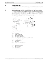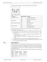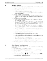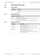
18
en | Camera Tilt and Pivot Adjustments
UMS Series Public View System
F01U029703 | 1.0 | 2006.07
Installation Manual
Bosch Security Systems, Inc.
8.2
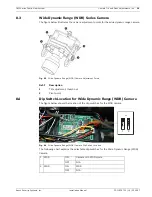
Dip Switch Location for the High-resolution Color Camera
The camera module has various settings for any additional adjustments that may be required.
See the illustration below and
Figure 8.4
on page 19 for the correct camera series settings and
dip switch locations.
Fig. 8.2
High-resolution, Color Camera Dip Switch Location
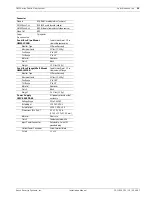
The following chart explains the selectable dip switches and their respective functions for the
High-resolution Color Camera:
1 IRIS DC
DC
IRIS
AES AES
2 Flickerless (FL)
ON
Shutter speed to be fixed at 1/100 second
OFF Normal
position
3 Backlight
Compensation
(BLC)
ON
Set to this position when a strong light is in the background
OFF Normal
position
4 Synchronization
Mode
INT
Internal Synchronization mode
L.L. Linelock
mode


