


8-6
Determination of Appropriate Power Supply Units
Rexroth IndraDrive
DOK-INDRV*-HMV-*******-PR01-EN-P
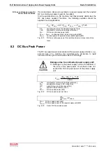
The auxiliary capacitor must be designed so that it is capable of storing
rotary drive energy:
tern
HMV01.1Ein
C
1000
*
2
ZW
U
2
B
U
rot
2W
Zu
C
−
−
≥
U
B
:
bleeder actuation threshold (approx. 820 V)
U
ZW
:
DC bus nominal voltage
W
rot
:
rotatory energy [Ws]
C
Zu
:
auxiliary capacitor [mF]
C
HMV01.1Ein intern
: internal capacitance of supply unit [mF]
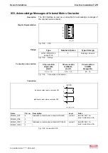
Fig. 8-17:
Required auxiliary capacitance
In power supply units with regulated DC bus voltage (HMV01.1R)
approximately 75 Ws per mF auxiliary capacitance can be stored.
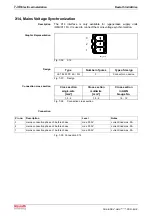
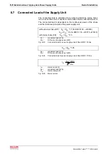
In power supply units with unregulated DC bus voltage (HMV01.1E) the
auxiliary capacitance should be designed for 10% overvoltage. The
storable energy per mF auxiliary capacitance is listed in the table below.
Mains voltage
3 x AC 380 V
3 x AC 400 V
3 x AC 440 V
3 x AC 480 V
storable energy per mF auxiliary capacitance
163 Ws
144 Ws
103 Ws
89 Ws
Fig. 8-18:
Storable energy with auxiliary capacitance on an HMV01.1E
8.5
Continuous Regenerated Power
The average sum of the continuous regenerated power of all drives may
not exceed the continuous regenerated power in the HMV01.1R or the
continuous bleeder power in the HMV01.1E.
Note:
For operation with continuous power, an additional load
caused by DC bus short circuit is no longer allowed.
The processing time in servo drive applications given a typical NC
machine tool, is relatively long in terms of the entire cycle time. There is
little regenerated continuous power. An exact calculation is generally not
required. It suffices if the peak regenerated power is not exceeded.
An exact calculation is needed in specific cases such as, for example:
•
servo drive applications with numerous accel / decel procedures such
as is the case in nibble machines and rollers
•
machine tools with modular main drives
•
applications in which excessive masses must be lowered as is the
case with those overhead gantries used with storage and transport
technologies
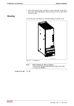
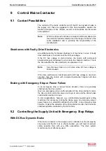
To calculate continuous regenerated power, the rotary energy of the
drives and the potential energy of non-compensated masses must be
known.
z
*
60
2
*
n
*
2
J
W
2
eil
g
rot
π
=
W
rot
:
rotary energy [Ws]
n
eil
:
speed in rapid traverse [min
-1
]
J
g
:
moment of inertia (motor + load) [kgm²]
z:
number of decels per cycle
Fig. 8-19:
Rotary energy
Содержание Rexroth IndraDrive HMV01.1E-W0030
Страница 24: ...3 12 Safety Instructions for Electric Drives and Controls Rexroth IndraDrive DOK INDRV HMV PR01 EN P Notes ...
Страница 28: ...4 4 Identifying and Checking the Delivered Components Rexroth IndraDrive DOK INDRV HMV PR01 EN P Notes ...
Страница 30: ...5 2 Transport and Storage Rexroth IndraDrive DOK INDRV HMV PR01 EN P Notes ...
Страница 40: ...6 10 Mechanical Mounting Rexroth IndraDrive DOK INDRV HMV PR01 EN P Notes ...
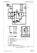
Страница 88: ...9 8 Control Mains Contactor Rexroth IndraDrive DOK INDRV HMV PR01 EN P Notes ...
Страница 121: ...Rexroth IndraDrive Appendix 13 21 DOK INDRV HMV PR01 EN P Dimensions Fig 13 24 HFD0x 2 480 0065 ...
Страница 122: ...13 22 Appendix Rexroth IndraDrive DOK INDRV HMV PR01 EN P Fig 13 25 HFD01 2 480 0026 ...
Страница 123: ...Rexroth IndraDrive Appendix 13 23 DOK INDRV HMV PR01 EN P Fig 13 26 HFD02 2 480 0026 ...
Страница 129: ...Rexroth IndraDrive Index 14 5 DOK INDRV HMV PR01 EN P X14 7 30 X2 7 22 X3 7 23 X31 7 25 X32 7 27 X33 7 29 ...
Страница 130: ...14 6 Index Rexroth IndraDrive DOK INDRV HMV PR01 EN P Notes ...
Страница 131: ......