


Rexroth IndraDrive
Electrical Installation
7-13
DOK-INDRV*-HMV-*******-PR01-EN-P
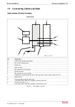
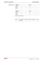
HMV01.1E-W0120
hmv_e120_front.fh7
L+
L-
+24 V
0 V
control voltage
DC bus
mains
PE connection
to drive controller
PE
PE connection
to drive controller
PE
X33
X32
X31
X2
X1
control panel
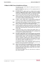
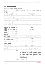
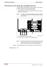
Fig. 7-9:
HMV01.1E-W0120
Description of connections:
Connection
See page
control voltage
7-15
DC bus
7-17
mains voltage (X5)
7-22
PE connection power supply unit resp. neighboring device
7-20
X1
7-21
X2
7-21
X3
7-27
X6
7-29
X7
7-25
Содержание Rexroth IndraDrive HMV01.1E-W0030
Страница 24: ...3 12 Safety Instructions for Electric Drives and Controls Rexroth IndraDrive DOK INDRV HMV PR01 EN P Notes ...
Страница 28: ...4 4 Identifying and Checking the Delivered Components Rexroth IndraDrive DOK INDRV HMV PR01 EN P Notes ...
Страница 30: ...5 2 Transport and Storage Rexroth IndraDrive DOK INDRV HMV PR01 EN P Notes ...
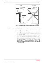
Страница 40: ...6 10 Mechanical Mounting Rexroth IndraDrive DOK INDRV HMV PR01 EN P Notes ...
Страница 88: ...9 8 Control Mains Contactor Rexroth IndraDrive DOK INDRV HMV PR01 EN P Notes ...
Страница 121: ...Rexroth IndraDrive Appendix 13 21 DOK INDRV HMV PR01 EN P Dimensions Fig 13 24 HFD0x 2 480 0065 ...
Страница 122: ...13 22 Appendix Rexroth IndraDrive DOK INDRV HMV PR01 EN P Fig 13 25 HFD01 2 480 0026 ...
Страница 123: ...Rexroth IndraDrive Appendix 13 23 DOK INDRV HMV PR01 EN P Fig 13 26 HFD02 2 480 0026 ...
Страница 129: ...Rexroth IndraDrive Index 14 5 DOK INDRV HMV PR01 EN P X14 7 30 X2 7 22 X3 7 23 X31 7 25 X32 7 27 X33 7 29 ...
Страница 130: ...14 6 Index Rexroth IndraDrive DOK INDRV HMV PR01 EN P Notes ...
Страница 131: ......