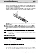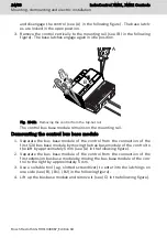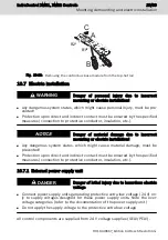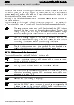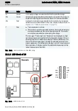
The LED block of 10 is positioned on the higher located area of the control hous-
ing.
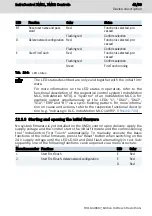
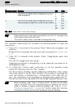
The following functions are assigned to the LEDs at running system firmware:
LED
Color
Function
s
Red/orange/green
Sercos status
DIA1
Red/orange/green
Used as feedback for the operation mode switch
DIA2
Red/orange/green
Basic diagnostics by the system
DIA3
Red
Currently booting
DIA4
Red
Currently booting
STA
Red/orange/green
STOP/READY/RUN
ERR
Red/orange/green
Error status (warning, error)
BT
Red/orange/green
Boot status
D
Red/orange/green
Onboard S20: Diagnostics S20 bus
E
Red/orange/green
Onboard S20: Error or warning of S20 devices
Tab. 12-2: LED block of 10
The displayed device states are firmware-dependent and described
in the functional description of the respective control system
(Rexroth IndraLogic XLC IndraMotion MLC 14 VRS, Functional De-
scription,
12.1.3 Operation mode switches
The operation mode switch is positioned on the higher located area of the con-
trol housing.
IndraControl XM21, XM22 Controls
37/69
Device description
R911340667_Edition 04 Bosch Rexroth AG
Содержание Rexroth IndraControl XM21
Страница 1: ...IndraControl XM21 XM22 Controls Operating Instructions R911340667 Edition 04 ...
Страница 6: ...IV IndraControl XM21 XM22 Controls Bosch Rexroth AG R911340667_Edition 04 ...
Страница 70: ...64 69 IndraControl XM21 XM22 Controls Bosch Rexroth AG R911340667_Edition 04 ...
Страница 73: ...IndraControl XM21 XM22 Controls 67 69 R911340667_Edition 04 Bosch Rexroth AG ...
Страница 74: ...68 69 IndraControl XM21 XM22 Controls Bosch Rexroth AG R911340667_Edition 04 ...
Страница 75: ...Notes IndraControl XM21 XM22 Controls 69 69 ...

