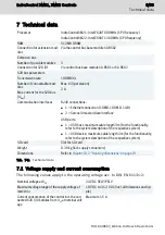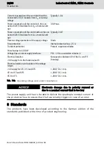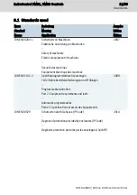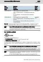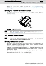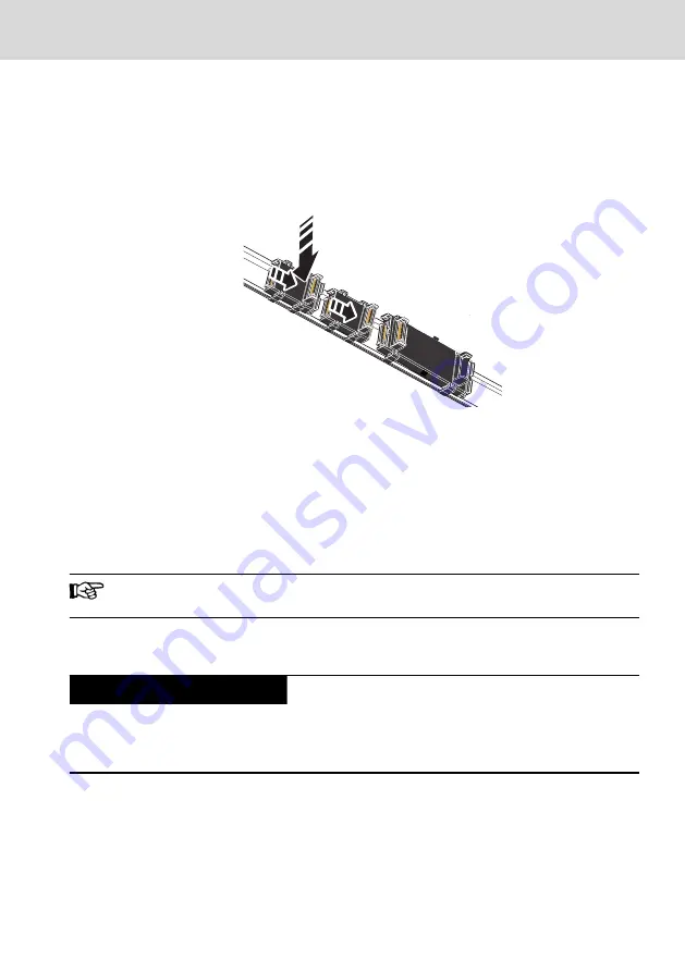
2. Move the first extension bus base module, (see (B) to the right and con-
nect the extension bus base module with the bus base module of the con-
trol (see (D) in the following figure).
3. Move the other extension bus base modules to the right until all bus base
modules are connected to each other (see (C) in the following figure).
A
B
D
C
Fig. 10-11: Interconnect extension bus base modules and connect them to the control
bus base module
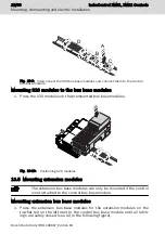
Mounting extension modules to the extension bus base modules
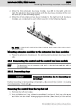
1. Press the extension modules on the premounted extension bus base mod-
ules.
10.6 Demounting the control and the control bus base module
To demount, use a common tool such a slotted screwdriver with a
2.5 mm blade.
10.6.1 Demounting steps
Component destruction due to demounting un-
der voltage!
NOTICE
Before mounting or demounting components, disconnect the control - including
its components - from voltage.
Removing the control from the top-hat rail
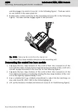
1. Remove the left end clamp.
2. Use a suitable tool (e.g. slotted screwdriver) and put it first into the upper
and then into the lower disengaging mechanism (base latch) of the control
IndraControl XM21, XM22 Controls
23/69
Mounting, demounting and electric installation
R911340667_Edition 04 Bosch Rexroth AG
Содержание Rexroth IndraControl XM21
Страница 1: ...IndraControl XM21 XM22 Controls Operating Instructions R911340667 Edition 04 ...
Страница 6: ...IV IndraControl XM21 XM22 Controls Bosch Rexroth AG R911340667_Edition 04 ...
Страница 70: ...64 69 IndraControl XM21 XM22 Controls Bosch Rexroth AG R911340667_Edition 04 ...
Страница 73: ...IndraControl XM21 XM22 Controls 67 69 R911340667_Edition 04 Bosch Rexroth AG ...
Страница 74: ...68 69 IndraControl XM21 XM22 Controls Bosch Rexroth AG R911340667_Edition 04 ...
Страница 75: ...Notes IndraControl XM21 XM22 Controls 69 69 ...

