


RE 92110-01-B/2022-03-22, Bosch Rexroth AG
About this product |
A4VSH series 1x and 30 21
/64
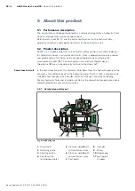
5�2�2 Functional description
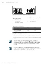
Torque and rotational speed are applied to the drive shaft (
1
) by a drive motor.
The drive shaft is connected by splines to the cylinder (
8
) to set this in motion.
With every revolution, the pistons (
9
) execute a stroke in the cylinder bores, the
size of which depends on the pitch of the cradle (
11
). The slipper pads (
10
) are
held on with the pistons and guided along the glide surface of the cradle by the
retaining plate (
2
).
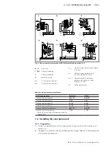
The pitch of the swashplate during a revolution causes each piston to move over
the bottom and top dead centers and back to its initial position.
Here, hydraulic fluid is fed in and drained out through the two control slots in
the control plate (
4
) according to the stroke displacement. On the high-pressure
side (
5
) the hydraulic fluid is pushed out of the cylinder chamber and into the
hydraulic system by the pistons. At the same time, hydraulic fluid flows into the
growing piston chamber on the low-pressure side (
6
). In a semi-closed circuit, this
is supported by the return flow and boost pressure or the anti-cavitation valves.
The swivel angle of the cradle (
11
) is infinitely variable. Controlling the swashplate
swivel angle changes the piston stroke and, therefore, the displacement.
Moving the swashplate across the neutral position will change the direction of flow
(making reversing operation possible). The swivel angle is controlled hydraulically
by the stroking piston (
3
). The cradle is mounted in swivel bearings for smooth
operation and the neutral position is spring-centered. Increasing the swivel angle
increases the displacement; reducing the angle reduces displacement accordingly.
Various control devices are available depending on requirements.
For information, see data sheet 92110 as well as the data sheets of the
respective controls, see Table 1 "Required and supplementary documentation"
on page 5.
Pump function
Control


