background image

11

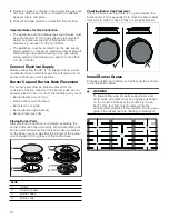
Check the Installation

Place each correct sized burner cap in its seated, 

notched position and check the operation of the electric 

igniters. Check flame characteristics. Flame should be 

blue with a minimal yellow tip on the outer cone of the 

flames.

Checking Flame Characteristics

Note:  

If the flame is completely or mostly yellow, verify 

that the regulator is set for the correct fuel. After 

adjustment, retest.
Some yellow streaking is normal during the initial start-

up. Allow unit to operate 4-5 minutes and re-evaluate 

before making adjustments.

Conversion to LP Gas

The components required for this are contained in the 

conversion kit included with this appliance, or are 

available from Customer Service.

Important:

 After finishing, attach the sticker indicating 

the new gas type close to the rating label if you change 

to LP Gas, or remove the sticker if you are changing 

back to Natural Gas. 

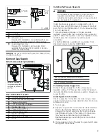
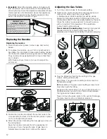
Converting the Pressure Regulator

Locate the pressure regulator on the bottom right end of 

the cooktop.

Note:  

The arrow on the back of the regulator must point 

in the direction of the gas flow to the cooktop.

1.

Remove the hexagon shaped cap from the regulator 

making sure not to dislodge the gasket on the cap or 

the spring inside the regulator.

2.

Grasp the plastic button stem firmly and pull it 

forcefully from the metal cap. The stem snaps snugly 

into an indent in the cap and may require a strong pull 

to remove. (Hint: it may be helpful to gently “rock” the 

plastic stem while pulling it from the metal cap.)

3.

After removing the stem from the cap, rotate the stem 

180° so the button end of the stem is away from the 

cap and the letters “LP” on the stem are upside down 

when the cap is set flat on its head. Snap the stem 

back in place in this position inserting it into the indent 

in the metal cap.The stem should snap into place.

Yellow Flames:

Further adjustment is 

required.

Yellow Tips on Outer 

Cones:

Normal for LP Gas

Soft Blue Flames:

Normal for Natural Gas

A

Spring

B

Plastic button stem

C

Gasket

$

&

%

$

%

Содержание NGM8657UC

Страница 1: ...Installation Manual Gas Cooktop NGM8657UC ...

Страница 2: ...t Gas Supply 9 Connect Electrical Supply 10 Burner Cap and Burner Base Placement 10 Install Burner Grates 10 Check the Installation 11 Conversion to LP Gas 11 Converting the Pressure Regulator 11 Replacing the Nozzles 12 Adjusting the Gas Valves 12 Customer Service 13 9 Safety DefinitionsSafetyDefinitions 9 WARNING This indicates that death or serious injuries may occur as a result of non observan...

Страница 3: ...WKH JDV VXSSOLHU V LQVWUXFWLRQV I RX FDQQRW UHDFK RXU JDV VXSSOLHU FDOO WKH ILUH GHSDUWPHQW QVWDOODWLRQ DQG VHUYLFH PXVW EH SHUIRUPHG E D TXDOLILHG LQVWDOOHU VHUYLFH DJHQF RU WKH JDV VXSSOLHU 51 1 I WKH LQIRUPDWLRQ LQ WKHVH LQVWUXFWLRQV LV QRW IROORZHG H DFWO D ILUH RU H SORVLRQ PD UHVXOW FDXVLQJ SURSHUW GDPDJH SHUVRQDO LQMXU RU GHDWK 1HYHU 2SHUDWH WKH 7RS 6XUIDFH RRNLQJ 6HFWLRQ 51 1 RI WKLV SSOLD...

Страница 4: ...National Fuel Gas Code ANSI Z223 1 NFPA 54 or in Canada the Natural Gas and Propane Installation Code CSA B149 1 The appliance must be electrically grounded in accordance with local codes or in the absence of local codes with the National Electrical Code NFPA 70 latest edition or in Canada the Canadian Electric Code CSA C22 1 02 Electric Safety WARNING Before you plug in an electrical cord or turn...

Страница 5: ...es Installer show the owner where the gas shut off valve is located Related Equipment Safety The appliance should only be used if installed by a qualified technician in accordance with these installation instructions The manufacturer is not responsible for any damage resulting from incorrect installation Remove all tape and packaging before using the appliance Destroy the packaging after unpacking...

Страница 6: ... VAC connection Plan the installation so that the power connection is accessible from the front of the cabinet Gas Requirements The cooktop is shipped from the factory for use with natural gas For use with LP conversion a certified technician or installer must do the conversion Supply Pressure Natural Gas 7 inches water column 17 4 Millibars Propane Gas 11 inches water column 27 4 Millibars The pr...

Страница 7: ... has been made Note All measurements given must be precisely followed If nonstandard cabinets are used make sure they are installed with minimum dimensions shown in the following image for installation in a kitchen island Ventilation Requirements We strongly recommend the installation of ventilation with the appliance The appliance must be installed according to the ventilation instructions 9 CAUT...

Страница 8: ...mable intermediate floor e g metal or plywood 3 8 10 mm from the base of the cooktop This will prevent access to the base of the cooktop The distance from the intermediate floor to the power supply connection for the appliance must be at least 3 8 10 mm Install the Cooktop 9 WARNING Before you plug in an electrical cord or turn on power supply make sure all controls are in the OFF position 9 CAUTI...

Страница 9: ...gulator Always use a new flex line Checking Gas Line for Leaks Check supply line connections for leaks using a soap solution or non corrosive leak detection fluid Do not use a flame of any sort 1 Turn on gas 2 Apply a soap solution or non corrosive leak detection fluid to all joints and fittings in the gas connection between the shut off valve and the cooktop Include gas fittings and joints in the...

Страница 10: ...ner parts are not properly placed one or more of the following may occur Burner flames are too high Flames shoot out of burners Burners do not ignite Burner flames light unevenly Burner emits gas odor Placing Burner Parts After electrical connection is complete assemble the burner parts correctly and evenly When assembling the burner parts make sure that the burner head is placed on the base in su...

Страница 11: ...Converting the Pressure Regulator Locate the pressure regulator on the bottom right end of the cooktop Note The arrow on the back of the regulator must point in the direction of the gas flow to the cooktop 1 Remove the hexagon shaped cap from the regulator making sure not to dislodge the gasket on the cap or the spring inside the regulator 2 Grasp the plastic button stem firmly and pull it forcefu...

Страница 12: ...2 Remove the control knobs from the gas valves and remove the white ring that is underneath A flexible black rubber sealing ring will be visible Below the left upper position of that seal there is a visible black Star T10 screw partly hidden by the seal Press the rubber seal aside a bit to meet the screw with a long thin T10 screwdriver The dual flame burner has 2 setting screws Never remove the s...

Страница 13: ... number for your appliance available You can find this information on the rating label in the Appliance Document List on the underside of the appliance Gas Pressure wc BTU h kW M valve adjustment screw setting Natural gas 7 77 3400 1 B Propane 11 54 3400 1 A Natural gas 7 102 6000 1 76 B Propane 11 71 6000 1 76 A Natural gas 7 125 9010 2 64 B Propane 11 88 9010 2 64 A Natural gas 7 1 161 17000 4 9...

Отзывы: