background image


F.01U.331.565-01 

© 2016 Bosch Security Systems, Inc. 

Detector symbol showing cable access at 
top 


1.


With the weld symbol visible, attach the ISN-GMX-P0 to 
the mounting surface using two fillet welds as shown 
(Fig. 3, item B). 
If welding is not possible, use the ISN-GMX-P0 as a drill 
template. 


Mark the 3 centrally located countersunk holes (Fig. 
3, item A). 


Drill 3 x 3.2mm Ø holes (depth to be determined by 
the thickness of the mounting surface). 


Thread to M4. 


Secure the ISN-GMX-P0 using 3 x M4 countersunk 
screws (provided with ISN-GMX-P0). 

2.


Mount the detector on to the ISN-GMX-P0. 

3.


Mount the ISN-GMX-S1 internal test transmitter on the 
designated location on the ISN-GMX-P0 (Fig. 3, item C) 
and connect to the detector (Fig. 1, item E). 

5.3.


Installation on concrete using the ISN-GMX-P0 
mounting plate 

Use the drill symbol side of the ISN-GMX-P0 mounting plate 
(Fig. 4) to install the detector on concrete surfaces. 


The ISN-GMX-P0 mounting plate can be used for 
installing a seismic detector on a concrete surface. 
It is essential to use the correct side and mounting 
methods. The ISN-GMX-P0 displays a detector 
symbol to indicate the direction of the cable access 
to the detector. 


Take note of the orientation of the ISP-SM90-120 
seismic detector and the required orientation of 
the ISN-GMX-P0 mounting plate. 


ISN-GMX-P0 drill symbol 


Detector symbol showing cable access at 
top 


1.


Use the ISP-SM90-120 drilling template (provided) to 
determine the location of the required holes. 

2.


Drill a 10mm Ø x 60mm hole and insert the steel 
expansion plug. 

3.


Drill a 5mm Ø x >22mm hole and insert the ISN-GMX-S1 
brass expansion plug. 


When installing on concrete, the ISN-GMX-S1 must 
not have any contact with the ISN-GMX-P0 
mounting plate. The ISN-GMX-S1 must be attached 
to the concrete using the M4 x 21mm screw and the 
associated brass expansion plug. 

4.


Secure the ISN-GMX-P0 to the steel expansion plug with 
the M6 x 47mm screw. 

5.


Secure the ISN-GMX-S1 to the brass expansion plug with 
the M4 x 21mm screw. 

6.


Mount the detector on to the ISN-GMX-P0. 

6.


Mounting the detector 

1.


Remove the cover from the detector. 

2.


Attach the detector to the prepared mounting base using 
the two mounting screws (Fig. 1, items I). 

3.


Remove the cable access skirt (Fig. 5). 

4.


Wire the connection cables to the terminal (Fig. 1, item 
B) as shown in diagram (Fig. 6). 

5.


Secure the cable to a cable anchor (Fig. 1, items C) with 
a cable tie (provided). 

6.


Connect the accessories and program the detector. 

7.


Remove the pre-formed cable access points as required 
to enable cable access through the skirt (Fig. 5). 

8.


Replace the cable access skirt. 


The cables connected to terminals 8, 10 and 11 
must not exceed 3m in length. 
The polarity of the LSN Bus must be maintained. 
The screen from the LSN cables must be connected 
into terminal 7. 

7.


Accessories 

All of the accessories (Fig. 7) have their own installation 
instructions, which are supplied with each accessory. These 
installation instructions should be followed for the correct 
installation and optimum performance from this seismic 
detector. For ordering information, see section 16. 

8.


Configuration (addressing LSNi/LSN) 

ISP-SM90-120 supports LSNi (LSN improved) and LSN (LSN 
classic). The detector must be configured using the two DIP 
switches (Fig. 1, items G and J) before the power supply is 
connected via the LSNi/LSN bus. The DIP switches are used 
for configuration and addressing as follows: 


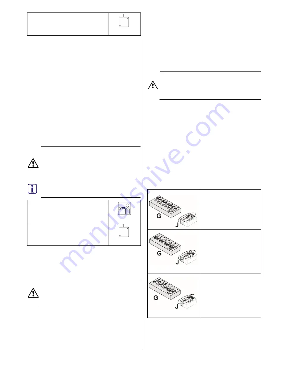
Fig. 1, item G – Addressing 


Fig. 1, item J – Material and coverage application 

The following configurations are possible: 


LSN application 
Fig. 1, item G all in ON 
position 
Fig. 1, item J in ON position 
(default setting) 


LSNi application with 
automatic addressing 
Fig. 1, item G all in OFF 
position 
Fig. 1, item J in ON position 


LSNi application with 
manual addressing 
Fig. 1, item G set to the 
corresponding address (see 
the table in the Appendix at 
the end of this document). 
Fig. 1, item J ON position 

Содержание ISP-SM90-120

Страница 1: ...F 01U 331 565 01 1 2016 Bosch Security Systems Inc ISP SM90 120 en Seismic detector de Körperschallmelder 11 2016 1 2 3 4 5 6 ...

Страница 2: ...F 01U 331 565 01 2 2016 Bosch Security Systems Inc 7 ...

Страница 3: ...ategy 4 1 Detector spacing distance Detectors should be positioned so that they cover the entire area to be monitored The distance between detectors is referred to as the spacing distance sd Detector spacing distance sd To ensure complete coverage of the protected area the following formula should be applied to determine the correct spacing distance between seismic detectors Spacing distance sd op...

Страница 4: ...g 4 Secure the ISN GMX P0 to the steel expansion plug with the M6 x 47mm screw 5 Secure the ISN GMX S1 to the brass expansion plug with the M4 x 21mm screw 6 Mount the detector on to the ISN GMX P0 6 Mounting the detector 1 Remove the cover from the detector 2 Attach the detector to the prepared mounting base using the two mounting screws Fig 1 items I 3 Remove the cable access skirt Fig 5 4 Wire ...

Страница 5: ...of the detector It is only possible to set the shock sensitivity for the mode and effective radius independently in USER MODE with the LSNi LSN control panel Mode Effective radius Shock sensitivity Example of use Concrete 5m High Vault Mode Effective radius Shock sensitivity Example of use Concrete 4m High Vault modular vault Concrete 2 5m High Vault modular vault Steel 2m Medium Armor plated safe...

Страница 6: ...ts must be seamlessly welded 6 Avoid mounting detectors on modules to which guide rails for cassette transport lifts ventilators or other mechanical equipment are attached 7 Always equip modules which have a pay in withdrawal slot with a detector This will also be able to monitor the adjacent modules 8 All doors must always be equipped with a detector 9 Programming Recommended setting On maximum 5...

Страница 7: ...bstand zwischen den Meldern wird als Melderabstand bezeichnet sd engl spacing distance Melderabstand sd Für eine vollständige Abdeckung des zu schützenden Bereichs sollte die folgende Formel angewendet werden um den korrekten Abstand zwischen den Körperschallmeldern zu bestimmen Melderabstand sd Wirkradius r 2 0 75 Beispiel Material Wirkradius Melderabstand Stahl 2m 3m Beton 4m 6m LWS Panzerungssy...

Страница 8: ... Montage auf Beton darf der ISN GMX S1 keinen Kontakt mit der Montageplatte ISN GMX P0 haben Der ISN GMX S1 muss mithilfe der Schraube M4 21 mm und dem dazugehörigen Messingspreizdübel am Beton befestigt werden 4 Befestigen Sie die ISN GMX P0 mithilfe der Schraube M6 47 mm am Stahlspreizdübel 5 Befestigen Sie den ISN GMX S1 mit der Schraube M4 21 mm am Messingspreizdübel 6 Montieren Sie den Melder...

Страница 9: ...lung reduziert Eine potentielle Anwendung ist die Verhinderung der Alarmauslösung bei starken funktionsbedingten Geräuschen 9 Programmierung über LSNi LSN Zentrale Die Programmierung des Melders erfolgt über die Konfigurationssoftware der entsprechenden Zentrale 10 Wirkradius Der angegebene Wirkradius gilt für einen Angriff mit Sauerstofflanze Bei einem Angriff mit mechanischem Werkzeug z B Bohrer...

Страница 10: ... Thema 14 Elementtresore Beim Einsatz des Körperschallmelders in und an Elementtresoren aus Stahl und Betonmaterial sind folgende Grundsätze unbedingt zu beachten Stärke von 100 bis 400 mm Breite bis 1 000 mm Länge bis 6 500 mm Elemente mit Melderanordnung Eckverbindung Wand Wand durchgehend verschweißt Immer 1 Melder an Türen 1 Ein Melder für jeweils maximal 5 Wandelemente Der Melder muss auf dem...

Страница 11: ...htigkeit EN 60721 nicht kondensierend 95 Zulassungen Siehe Typenschild auf Innenseite der Abdeckung Abb 5 16 Bestellangaben ISP SM90 120 Körperschallmelder F 01U 173 560 ISN GMX P0 Montageplatte F 01U 003 366 ISN GMX S1 Interner Prüfsender F 01U 003 371 ISN GMX W0 Wand Deckeneinbaudose F 01U 003 372 ISN GMX B0 Bodeneinbaudose F 01U 003 365 ISN GMX P3S Schlossschutz F 01U 003 368 ISN GMX P3SZ Schlo...

Страница 12: ...1 1 1 0 1 1 209 1 1 0 1 0 0 0 1 38 0 0 1 0 0 1 1 0 124 0 1 1 1 1 1 0 0 210 1 1 0 1 0 0 1 0 39 0 0 1 0 0 1 1 1 125 0 1 1 1 1 1 0 1 211 1 1 0 1 0 0 1 1 40 0 0 1 0 1 0 0 0 126 0 1 1 1 1 1 1 0 212 1 1 0 1 0 1 0 0 41 0 0 1 0 1 0 0 1 127 0 1 1 1 1 1 1 1 213 1 1 0 1 0 1 0 1 42 0 0 1 0 1 0 1 0 128 1 0 0 0 0 0 0 0 214 1 1 0 1 0 1 1 0 43 0 0 1 0 1 0 1 1 129 1 0 0 0 0 0 0 1 215 1 1 0 1 0 1 1 1 44 0 0 1 0 1 1...

Отзывы: