12
| English
1 609 92A 1A4 | (12.5.15)
Bosch Power Tools
Declaration of Conformity
We declare under our sole responsibility that the product de-
scribed under “Technical Data” is in conformity with all rele-
vant provisions of the directives 2011/65/EU, until
19 April 2016: 2004/108/EC, from 20 April 2016 on:
2014/30/EU, 2006/42/EC including their amendments and
complies with the following standards: EN 61029-1,
EN 61029-2-6.
Technical file (2006/42/EC) at:
Robert Bosch GmbH, PT/ETM9,
70764 Leinfelden-Echterdingen, GERMANY
Robert Bosch GmbH, Power Tools Division
70764 Leinfelden-Echterdingen, GERMANY
Leinfelden, 04.05.2015
Assembly
Before any work on the machine itself, pull the mains
plug.
Mounting the Carrying Handle
Before first-time use, securely fit the carrying handle
12
to
the power tool using the internal hex screws
13
.
Clamping In Drill Stand for Diamond Drills
GCR 350
The safety and operating instructions for the drill stand
being used are to be strictly observed!
For mounting the power tool into the drill stand, please read
and observe the operating instructions of the drill stand.
Inserting/Replacing the Core Bit
Before any work on the power tool, during work breaks
and when not using the power tool, secure the power
tool against unintentional movement by tightening the
parking brake 5.
To do so, read and follow the operating
instructions of the drill stand.
Inserting a Core Bit
Examine the core bit before inserting it. Use only core
bits that are in perfect condition.
Damaged or deformed
core bits can lead to dangerous situations.
Clean the core bit before inserting it. Apply a light coat of
grease to the core bit thread or spray on a corrosion protec-
tion agent.
Screw a 1 1/4"-UNC core bit
9
onto the drill spindle
10
.
Check the proper seating of the core bit.
Incorrectly or
unsecurely fastened core bits can become loose during op-
eration and may pose a danger.
Removing a Core Bit
Wear protective gloves when replacing the core bit.
The core bit can become hot after prolonged operation of
the power tool.
Loosen the core bit
9
using an open-end spanner (size
41 mm). When doing so, hold a second open-end spanner
(size 32 mm) on the two flats of the drill spindle
10
to provide
counterforce.
The easy-release element
11
makes it easier to release the
core bit
9
.
Connecting the Water Cooling
When wet-drilling core bits are not sufficiently cooled during
drilling, the diamond segments can become damaged or the
core bit can become jammed in the bore hole. Therefore, pro-
vide for a sufficient water supply during wet drilling.
When boring out a given bore, the given bore must be careful-
ly plugged in order to enable sufficient cooling of the core bit.
Connected hoses, shut-off valves or accessories must
not obstruct or hinder the drilling process.
Shut the water cock
8
. Connect water supply to the water-out-
let connector
7
. The water supply is possible either via a mo-
bile water-pressure container (accessory) or via stationary
water connection.
You require a water collection ring and a wet/dry vacuum
cleaner (both accessories) to collect the water escaping from
the bore hole during wet drilling.
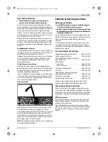
When wet drilling overhead, the escaping water must
be collected.
To do this, insert the power tool into a drill
stand and mount a water collecting ring.
Read and observe the operating instructions of the water col-
lection ring to mount it.
Operation
Starting Operation
Observe the mains voltage!
The voltage of the power
source must correspond with the data on the type plate of
the machine.
Before beginning work, consult the structural engi-
neer, architect or construction supervisor in charge.
Only cut through reinforcements with the permission
of a structural engineer.
When core drilling through walls or floors, ensure to
check the respective rooms/enclosures for obstruc-
tions. Barrier off the construction site and secure the
drilled out core against falling down with the use of cas-
ing or similar.
Function test of the portable residual current device
(PRCD)
Each time before beginning work, check that the portable re-
sidual current device (PRCD)
2
is functioning properly:
– Press the
“TEST”
button on the portable residual current
device (PRCD). The red control indicator extinguishes.
– Press the
“RESET”
button. It must now be possible to
switch the power tool on.
Henk Becker
Executive Vice President
Engineering
Helmut Heinzelmann
Head of Product Certification
PT/ETM9
OBJ_BUCH-2203-002.book Page 12 Tuesday, May 12, 2015 9:22 AM


