background image

Product Information


Gaz 6000 W – 6720866247 (2019/07)

8

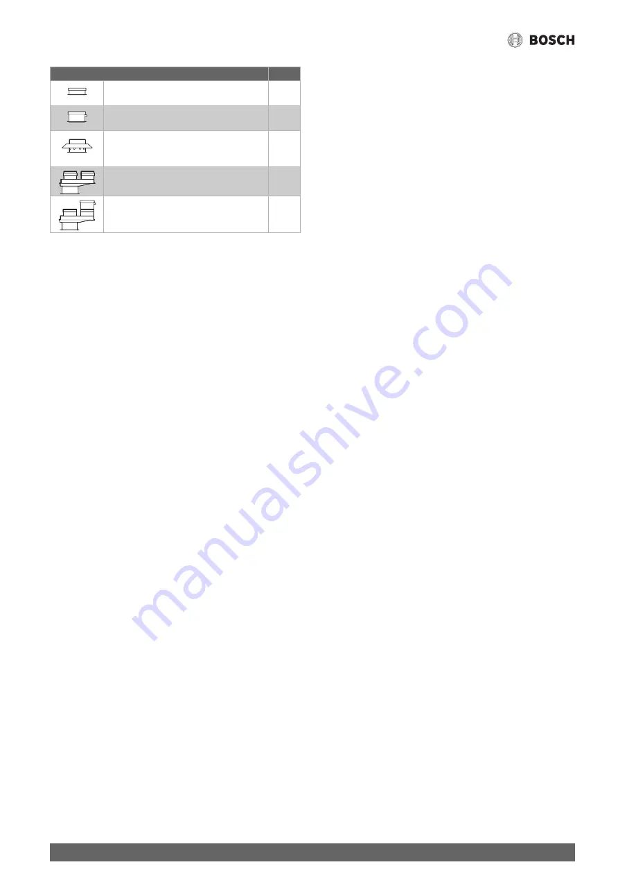
Table 5 Clearance B depending on the flue accessories for vertical flue 

pipe

Flue gas accessories

B [mm]

Ø 60/100 mm

Connection adapter Ø 60/100 mm

≥ 170

Ø 60/100 mm

Vertical condensate drain Ø 60/100 mm

≥ 220

Ø 80 mm

Connection adapter Ø 60/100 mm with 
combustion air supply

≥ 200

Ø 80/80 mm

Separate pipe connection Ø 80/80 mm

≥ 210

Ø 80/80 mm

Separate pipe connection Ø 80/80 mm,
vertical condensate drain Ø 80 mm

≥ 290

Содержание Gaz 6000 W

Страница 1: ...6720866247 2019 07 EG TN DZ MA Installation and maintenance instructions for the contractor Wall mounted gas boiler Gaz 6000 W 0 010 010 989 001 WBN 6000 24 28 35 CR HR N L ...

Страница 2: ...the DHW heating 23 7 5 1 Adjust the domestic hot water temperature 23 7 6 Setting the heating controls 23 7 7 After commissioning 23 7 8 Setting summer mode 23 8 Shutdown 24 8 1 Switching off standby mode 24 8 2 Setting frost protection 24 8 3 Anti block protection 24 9 Thermal disinfection WBN 6000 HR only 25 10 Heating pump 25 10 1 Changing the heating pump curve 25 11 Settings in the service me...

Страница 3: ...2019 07 18 1 Commissioning report for the device 42 18 2 Electrical wiring 44 18 3 Technical Data 45 18 4 Sensor values 47 18 4 1 Flow temperature sensor 47 18 4 2 DHW temperature sensor 47 18 5 Setting values for central heating DHW output 48 ...

Страница 4: ...installation instructions heat source heating controller etc before installation Observe the safety instructions and warnings Follow national and regional regulations technical regulations and guidelines Record all work carried out H Determined use The product may only be used in a domestic situation for the heating of central heating water and for DHW heating in closed loop DHW and heating system...

Страница 5: ...on location meets the ventilation requirements Do not repair manipulate or deactivate safety relevant components Only install original spare parts Check for gas tightness after working on gas carrying components H Electrical work Electrical work must only be carried out by electrical installation contractors Before starting electrical work Isolate all poles of the mains voltage and secure against ...

Страница 6: ... data plate location can be found in the product overview Additional type plate The product name and the most important product data are shown on the additional data plate The additional type plate can be found on the outside of the product in an easily accessible location 2 4 Overview of types WBN 6000 CR appliances are combi boilers for central and instantaneous DHW heating WBN 6000 HR appliance...

Страница 7: ...60 634 68 100 S K 345 400 300 Wallthickness S K mm for Ø flue accessories mm Ø 60 100 Ø 80 Ø 80 125 15 24 cm 130 110 155 24 33 cm 135 115 160 33 42 cm 140 120 165 42 50 cm 145 145 170 Flue gas accessories A mm Ø 60 100 mm Connection elbow Ø 60 100 mm 95 Ø 60 100 mm Connection adapter Ø 60 100 mm elbow 90 Ø 60 100 mm 185 Ø 80 mm Connection adapter Ø 60 100 mm with combustion air supply elbow 90 Ø 8...

Страница 8: ...lue gas accessories B mm Ø 60 100 mm Connection adapter Ø 60 100 mm 170 Ø 60 100 mm Vertical condensate drain Ø 60 100 mm 220 Ø 80 mm Connection adapter Ø 60 100 mm with combustion air supply 200 Ø 80 80 mm Separate pipe connection Ø 80 80 mm 210 Ø 80 80 mm Separate pipe connection Ø 80 80 mm vertical condensate drain Ø 80 mm 290 ...

Страница 9: ...12 Control device 13 Filling device WBN 6000 CR 14 Plate heat exchanger for Combi boilers WBN 6000 CR 15 Data plate 16 Pressure switch 17 Flame sense electrode 18 Flow temperature sensor 19 Heat exchanger temperature limiter 20 Air baffle 21 Differential pressure switch 22 Combustion air inlet 23 Flue pipe 24 Hot water temperature sensor 25 Pressure relief valve cold water WBN 6000 CR 26 Flow mete...

Страница 10: ...cordance with the regulations please observe all the applicable national and regional regulations as well as all technical rules and guidelines The document 6720807972 contains information about the applicable regulations You can use the document search on our website to display this You will find the address of the website on the back of these instructions ...

Страница 11: ...iciency of the appliance the water vapour contained in the flue gas may condense in the flue pipe Install a condensate pipe if required Inthiscase installhorizontalfluepipeswithadownwardslopetothe applianceof5 2 sothatthecondensate canrunoffinthedirection of the condensate pipe Table 6 The flue gas routing must correspond to B22 for an open flue or C12 C32 C42 C52 or C82 for balanced flue operatio...

Страница 12: ...m lengths Each additional 90 elbow is equivalent to 2 m Each additional 45 elbow is equivalent to 1 m Table 7 B22 horizontal flue gas routing 4 3 2 B22 vertical flue gas routing Fig 5 B22 vertical flue gas routing NOTICE Poor combustion if restrictor is not installed If B22 flue gas routing is used and appliance output 35 kW install restrictor accessory 7 736 995 123 If B22 vertical flue gas routi...

Страница 13: ...count in the maximum lengths Each additional 90 elbow in the flue pipe is equivalent to 2 m Each additional 45 elbow in the flue pipe is equivalent to 1 m Each additional 90 elbow in the combustion air pipe is equivalent to 1 m Each additional 45 elbow in the combustion air pipe is equivalent to 0 5 m Table 10 C12 C42 C82 horizontal flue gas routing with separate pipe L m Fan stage Natural Gas LPG...

Страница 14: ...w is equivalent to 0 5 m Table 11 C32 vertical flue gas routing with concentric pipe 4 3 6 C32 C52 vertical flue gas routing with separate pipe Fig 9 C32 vertical flue gas routing with separate pipe L1 Combustion air pipe length L2 Flue length L m Fan stage WBN 6000 24 1 5 6 1 5 2 5 9 2 5 5 11 5 8 18 WBN 6000 28 1 5 7 1 5 2 5 13 2 5 5 14 5 8 20 WBN 6000 35 1 5 1 1 5 2 5 2 2 5 5 3 5 7 18 L 0 010 00...

Страница 15: ...nt to 1 m Each additional 90 elbow in the combustion air pipe is equivalent to 1 m Each additional 45 elbow in the combustion air pipe is equivalent to 0 5 m Table 12 C32 C52 vertical flue gas routing with separate pipe L L1 L2 m L2 m Fan stage WBN 6000 24 4 2 5 4 10 2 5 9 10 18 5 9 13 18 24 9 12 16 24 30 12 15 18 WBN 6000 28 4 2 5 4 10 2 5 7 10 18 5 9 10 18 24 9 12 15 24 30 12 15 16 WBN 6000 35 4...

Страница 16: ... Country specific regulations must be observed 5 2 Solar preheated water only WBN 6000 CR WARNING Risk of scalding from hot water DHW temperatures over 60 C can arise during solar operation and this can cause scalding Use a thermostatic DHW mixer from the Solar set accessories to limit the temperature to 60 C CAUTION Risk of system damage through excessively high temperatures Excessive temperature...

Страница 17: ... of the expansion vessel B Additional expansion vessel required If results are borderline determine precise vessel size Iftheintersectionisontherightbesidethecurve installanadditional expansion vessel 5 5 Installing the device Making drill holes and the wall opening Secure the mounting template supplied with the printed documents to the wall when doing so observe the minimum side clearances of 100...

Страница 18: ...filled with water Fig 16 Connections on the gas and water side accessories 1 Heating flow cock2 2 WBN 6000 HR appliances Cylinder flow WBN 6000 CR appliances DHW 3 Gas isolator2 4 WBN 6000 HR appliances Cylinder return WBN 6000 CR appliances Cold water tap2 5 Heating return valve2 6 Hose from the pressure relief valve heating circuit 7 WBN 6000 CR appliances Filling facility Filling and venting th...

Страница 19: ...0 W 6720866247 2019 07 Checking the gas line for tightness Close the gas isolator to protect the gas valve against damage from excess pressure Check all joints for tightness test pressure max 150 mbar Depressurise the system ...

Страница 20: ...0 cm from the bath shower If the cable is not long enough Remove the main power cord and replace it with a suitable one Table 16 Connection outside safety zones 1 and 2 Attach a suitable mains plug to the mains cable Insert plug into a grounded electrical socket or Securely connect the power cable to a manifold Connection inside safety zones 1 and 2 Remove the main power cord and replace it with a...

Страница 21: ...original power cables from the manufacturer The control device must be opened to connect the power cable Disconnect the ignition cable Remove cover Remove the old power cable Plug the connector for the new cable into the circuit board Insert the strain relief fitting into the casing Install the casing cover Install the ignition cable Fig 19 6 3 3 Connecting a cylinder temperature sensor WBN 6000 H...

Страница 22: ...en menu 2 L2 Press key or to call up service function 2 bd chapter 11 2 from page 27 Using the key switch to the service function The current value flashes on the display Press key or to set the required value Press key until the display shows The set value is stored and the display automatically changes to the higher level menu Press the K button Switching on Switch on the device with the K key T...

Страница 23: ... operating instructions for the heating controller used These will show you how to set the room temperature how to heat economically and save energy The Bosch TRZ200 CR10 CR50 OpenTherm controllers programmable heating controllers can be used 7 7 After commissioning Check the gas supply pressure page 31 Complete commissioning report page 43 7 8 Setting summer mode The heating pump and consequently...

Страница 24: ...imum flowtemperature toat least 40 C Section 7 4 or If you want to leave the device switched off mix Bosch approved anti freeze into the heating water Tab page 16 and drain the DHW circuit For further information see the heating controller operating instructions Device frost protection The device frost protection function switches the burner and heating pump on when the temperature in the installa...

Страница 25: ...sinfection via service function 1 2d page 27 Wait until the maximum temperature has been reached Open all DHW draw off points in sequence from the nearest to the farthest and draw off DHW until hot water at 70 C has been flowing from all draw off points for 3 minutes Restore the original settings 10 Heating pump 10 1 Changing the heating pump curve Thespeedoftheheatingpumpcanbechangedattheterminal...

Страница 26: ...ice function To select a service function press key or The display shows the service function To confirm the selection press the key The current setting flashes To change the setting press the key or To store press key until is displayed or To not store press key The next highest menu level is displayed Press key again The appliance returns to standard operation Opening the menu The description is...

Страница 27: ...tes at minimum output After 15 minutes the appliance reverts to the standard operating mode 04 The appliance runs for 15 minutes at maximum output After 15 minutes the appliance reverts to the standard operating mode Using this service function you can temporarily change the operating mode of the device 1 3b Time interval for stopping and restarting the burner 1 3 10 minutes The time interval dete...

Страница 28: ...setting 2 9A Permanent operating mode 00 Standard operation the device operates as specified by the control unit 01 The appliance runs at minimum output 02 The appliance runs at maximum output This function permanently sets an operating mode 2 9b Current fan speed Current fan speed in 1 s 2 9E WBN 6000 CR appliances Turbine signal delay 01 02 06 0 25 seconds Through spontaneous pressure change in ...

Страница 29: ...ct service function 2 8E in the second service menu and save value 1 The appliance starts in the default setting 2 0A Gas type for appliance type 00 Appliance for natural gas 01 Appliance for LPG This service function allows you to set the gas type In the case of a conversion 2 bd is set to 00 2 0b Ionisation current When the burner is running 1 A OK 1 A fault With burner switched off 1 A OK 1 A f...

Страница 30: ...tting after every conversion sec 12 2 12 2 Gas setting natural gas and LPG 12 2 1 Preparation Flip the control device down page 18 Mount the control device at the bottom of the appliance so that the gas train and the control device can be operated at the same time Fig 27 Control device mounted in the frame allowing the gas valve and control device to be operated at the same time The rated output c...

Страница 31: ... close the gas valve remove the U tube pressure gauge and tighten the sealing screw Fig 28 1 Release the sealing screw at the test nipple for the gas supply pressure Fig 28 5 and connect the pressure gauge Open the gas valve and switch on the wall mounted conventional gas boiler Select service function 1 2F and set operating mode 4 maximum rated heat output chapter 11 2 from page 27 Check the requ...

Страница 32: ...2F and set operating mode 0 Chapter 11 2 from page 27 or key Switch off the appliance Remove the flue gas probe Replace the plug 13 3 Checking the CO level in the flue gas Use a multi hole flue gas probe for the test Ensure heat transfer by opening the radiator valves or DHW tap Switch on the appliance and wait a few minutes Remove plug from flue gas test port Fig 28 1 Insertafluegasprobeasfarasit...

Страница 33: ...erved We use the best possible technology and materials for protecting the environment taking account of economic considerations Packaging Where packaging is concerned we participate in country specific recycling processes that ensure optimum recycling Allofourpackagingmaterialsareenvironmentallycompatibleandcanbe recycled Used appliances Used appliances contain valuable materials that can be recy...

Страница 34: ...t breaker and secure against unintentional reconnection H Risk of death from escaping flue gas Escaping flue gas can cause poisoning Check for leaks after working on flue gas carrying components H Risk of explosion from escaping gas Escaping gas can cause an explosion Close the gas isolator prior to working on gas carrying components Carry out tightness test H Risk of scalding from hot water Hot w...

Страница 35: ...removal electrical safety Always secure the casing with these screws Flip the control device down page 18 1 Remove both safety screws from the appliance front 2 Lift off the casing Fig 30 15 2 3 Checking the strainer in the cold water pipe WBN 6000 CR 1 Remove the clip 2 Pull out the pressure relief valve Fig 31 Removing the pressure relief valve heating circuit 1 Remove the clip 2 Pull out the in...

Страница 36: ... in water using a rinsing agent and reinstall it Find any bent fins on the heat exchanger and carefully bend them straight 15 2 6 Checking the expansion vessel The expansion vessel must be checked every year Depressurise the device Adjust the pre charge pressure of the expansion vessel to the static head of the heating system if necessary 15 2 7 Setting the heating system operating pressure Table ...

Страница 37: ...e clip 2 Lever out the DHW temperature sensor from below using a screwdriver 3 Disconnect the connector at the temperature sensor Fig 36 Removing the DHW temperature sensor 15 2 10 Unblocking the pump e g when commissioning the system Flip the control device down page 18 to access the pump Undo cap 1 A small amount of water may escape Turn shaft 2 with a screwdriver for approx half a turn Screw in...

Страница 38: ... system visually 4 Check the gas supply pressure page 31 mbar 5 Leak test on the gas and water side section 5 from page 16 6 Check the heat block page 36 7 Check the burner page 36 8 Check the electrodes page 36 9 Check the pre charge pressure of the expansion vessel for the static head of the heating system bar 10 Check the charge pressure of the heating system bar 11 Check the electrical wiring ...

Страница 39: ...urs during operation the display shows the H symbol and in certain cases the symbol and a fault code e g EA flashes If H and appear Press the key and hold it until the H and symbols are no longer displayed The device goes back into operation and the flow temperature is displayed If only H appears Switch the device off and on again with the K key The device goes back into operation and the flow tem...

Страница 40: ...place if required Check the operating pressure of the heating system Check the temperature limiter and replace if required Check the starting of the pump replace pump if required Check the fuse and replace if required page 20 Vent the device Check the heat exchanger on the water side and replace if required EA Flame not detected Check that the earth lead is correctly connected Check whether the ga...

Страница 41: ...k flue system Clean or repair if required Check gas settings replace gas valve if required Ignition too violent or poor Check gas type Check gas supply pressure and adjust if required Check power supply Check electrodes with cable Replace if required Check flue system Clean or repair if required Check gas settings replace gas valve if required For natural gas Check external gas flow monitor Replac...

Страница 42: ...t maximum rated output Notes regarding underpressure or overpressure operation Gas setting and flue gas test Set gas type Gas supply pressure mbar Gas static supply pressure mbar Set maximum rated output kW Set minimum rated output kW Gas flow rate at maximum rated output l min Gas flow rate at minimum rated output l min Net calorific value HiB kWh m3 CO2 at maximum rated output CO2 at minimum rat...

Страница 43: ...ate trap filled Leak test carried out on the gas and water sides Function check carried out Commissioningincludescheckingthesettingvalues avisualleaktestonthedeviceandafunctioncheckofboththedeviceanditscontrol Thesystem installer conducts a test of the heating system The system named above has been checked to the extent described ___________________________________________________________ Name of ...

Страница 44: ...WBN 6000 HR 10 Turbine WBN 6000 CR 11 Alarm signal connection 24 V DC max 40 mA 12 3 way valve 13 Heating pump 14 Hot water temperature sensor 15 230 V connecting lead 16 OTM connection or ON OFF controller 1 17 Connection for outside temperature sensor 18 Diagnostic interface 19 Fuses 20 Reactor 21 Ignition transformer 0 010 005 999 001 15 2 13 17 18 16 8 4 2 3 2 2 2 2 2 2 10 12 9 11 3 4 6 7 5 1 ...

Страница 45: ...10 10 10 10 Min flow pressure bar 0 3 0 3 0 3 0 3 DHW comfort class as per EN 13203 2 2 2 2 Calculation figures for calculating the cross sectional area as per EN 13384 Flue gas temperature 80 60 C max rated value C 142 147 125 130 Flue gas temperature 53 47 C min rated value C 63 64 65 67 Flue gas mass flow rate max rated value g s 16 6 16 8 16 5 18 7 Flue gas mass flow rate min rated value g s 1...

Страница 46: ...10 Min flow pressure bar 0 3 0 3 DHW comfort class as per EN 13203 3 3 Calculation figures for calculating the cross sectional area as per EN 13384 Flue gas temperature 80 60 C max rated value C 128 130 Flue gas temperature 53 47 C min rated value C 70 75 Flue gas mass flow rate max rated value g s 22 0 23 8 Flue gas mass flow rate min rated value g s 19 10 18 6 CO2 at max rated output 6 8 7 3 7 7...

Страница 47: ...ture sensor Table 33 DHW temperature sensor Temperature C 10 Resistance 0 33 242 10 19 947 20 12 394 30 7 947 40 5 242 50 3 548 60 2 459 70 1 740 80 1 256 90 923 Temperature C 10 Resistance 0 28 704 10 18 410 20 12 171 25 10 000 30 8 269 35 6 881 40 5 759 45 4 847 50 4 101 55 3 488 60 2 981 65 2 559 70 2 207 75 1 912 80 1 662 85 1 451 90 1 272 ...

Страница 48: ... 2 15 6 5 9 12 2 30 0 1 3 16 8 6 8 14 1 32 3 1 4 18 0 7 8 16 0 34 6 1 5 19 2 8 8 18 1 36 9 1 6 20 4 9 9 20 3 39 2 1 7 21 6 11 0 22 5 41 6 1 8 22 8 12 2 24 9 43 9 1 9 24 0 13 5 27 6 46 2 2 0 Burner pressure Gas rate mbar mbar l min kg h Gas type G20 23 G30 31 G20 23 G30 31 Wobbe index 15 C 1013 mbar kWh m 14 1 24 3 14 1 24 3 Net calorific value 15 C HiB kWh m 10 5 34 9 10 5 34 9 Output kW 8 4 1 1 2...

Страница 49: ...3 1 1 5 3 7 5 16 24 6 1 0 1 09 14 6 1 8 4 6 6 39 27 5 1 1 1 22 15 1 2 0 4 9 6 82 28 4 1 1 1 26 16 0 2 2 5 5 8 15 30 1 1 2 1 33 17 5 2 6 6 6 9 12 33 0 1 3 1 46 18 8 3 0 7 7 10 50 35 4 1 4 1 57 20 3 3 6 9 0 12 70 38 3 1 5 1 69 22 0 4 2 10 6 14 30 41 5 1 6 1 83 23 5 4 8 12 2 17 00 44 3 1 7 1 96 25 0 5 4 13 8 18 39 47 2 1 9 2 08 26 7 6 2 15 8 21 60 50 4 2 0 2 23 27 5 6 6 16 8 22 19 52 0 2 1 2 29 29 0 ...

Страница 50: ......

Страница 51: ......

Страница 52: ...Bosch Thermotechnik GmbH Junkersstrasse 20 24 D 73249 Wernau www bosch thermotechnology com ...

Отзывы: