Applications Manual FHP560 Controller
| 5
Bosch Thermotechnology Corp.
Data subject to change
Page____ of ____
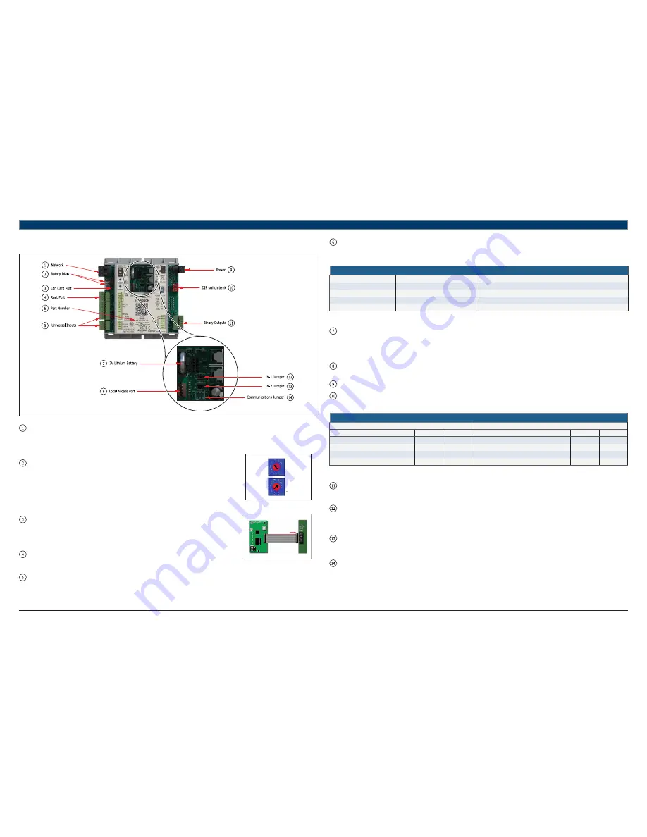
5 Controller Components & Features
Fig. 3 FHP560 Components
Network:
This block represents the communications port on the FHP560. The comm port can be con
fi
gured to communicate in two ways
(RS-485 or BACnet over ARC156) using the Communications Jumper. The communications wiring should be landed at the Net+, Net-,
and Shield terminals, ensuring the same polarity is maintained throughout the network segment. The “BAS Port Settings” DIP switch
is used to set the baud rate for the network, using the same baud rate for all controllers on the network. The LEDs (Rx and Tx)
fl
ash
repeatedly when the controller is communicating with the network.
Rotary Dials
: The rotary dials are used to address the FHP560 so it can be uniquely identi
fi
ed over a network.
Ones
Te
n
s
The top dial represents the Tens digit while the bottom one represents the Ones digit, allowing
for hardware-based addressing of up to address 99. Before setting or changing the address
make sure the FHP560 is powered off; the controller only reads the address when the module
is turned on. In the example shown in Fig. 4, the rotary dial is set to address 69.
Fig. 4 Rotary Dials
Lon Port:
For network integration applications involving the LonWorks network platform, the LON card
will be required to enable communication over this protocol. The card is ordered separately
and connects to the controller port as shown. Ensure that the communications jumper is in the
top position (EIA-485) and the BAS port settings are con
fi
gured using the DIP switch bank
(see DIP Switch).
Rnet Port:
The Rnet port is a four-connector block used mainly for wiring the ZS combo sensors to
the FHP560. It consists of 2 points for power (12VDC, Gnd) and 2 points for communication
(Rnet + and Rnet -). This port may also be used to hardwire a BACview6 module.
Fig. 5 Lon Connection
Part Number:
The FHP560 part number represents both the hardware and software components of the FHP560, and therefore changes if the
controller is ordered with a special software other than the standard (7.05.03) version.
Inputs:
There are 6 universal inputs on the FHP560. All inputs are capable of accepting thermistor (analog), pulse or dry contact (binary)
signals, but the
fi
rst 2 inputs (IN-1 and IN-2) are also capable of reading 0-5VDC signals; use the corresponding jumpers to select
between Therm/dry and 0-5V for these inputs. Refer to the “Ports Assignment and Overview” page for further details on con
fi
guring
these inputs.
Inputs
Input
Signal Type Supported
Description
IN-1 and IN-2
0-5Vdc
Input impedance of the FHP560 is approx. 30-kOhm
All
Thermistor
Precon type 2 (10-kOhm @ 77°F/25°C)
All
Dry Contact
3.3Vdc wetting voltage detects contact position
All
Pulse
Pulse counting up to 10 pulses per second.
Table 2
Battery:
The 10-year Lithium CR2032 3V battery retains data (e.g. control programs, modi
fi
ed parameters, schedules, etc) for a
maximum of 10,000 hours during power outages. If the FHP560 experiences RAM loss (e.g. due to low voltage on the controller
or high voltage on the network), it may be reset by recycling the battery power. This operation should be performed with the
FHP560 powered off (no 24Vac power), and resolves most of all “bad controller” issues. All previously saved parameters are
retained upon power up.
Local Access:
The local access port is available for system start-up, servicing and troubleshooting using a BACview Interface (handheld or
virtual) or Field Assistant.
Power:
Input power for the FHP560. 24Vac +/-10%, 50-60Hz; 20VA power consumption, Single Class 2 source only, 100VA or less.
DIP Switch:
The BAS Port Settings DIP switch bank is used to set the appropriate network con
fi
guration when the FHP560 is integrated into
a Building Automation System (BAS). The following table details the different settings available (this information is also on the
FHP560 label):
Available Settings
BAUD RATE SETTING
PROTOCOL
SW1
SW2
SW3
SW4
9.6kbps
Off
Off
BACnet® MS/TP
Off
Off
19.2kbps
Off
On
N2
On
Off
38.4kbps
On
Off
Modbus
Off
On
76.8kbps
On
On
Option Card (LON)
On
On
Table 3
Outputs:
The FHP560 has
fi
ve (5) binary outputs that can each be connected to a maximum of 24Vac/26Vdc. Each output is a dry contact
(Form A) rated at 1A, 24V max. Refer to the “Ports Assignment and Overview” page for further details on con
fi
guring these
outputs.
IN-1 Jumper:
This two-position jumper is used to set the input type selection for IN-1 as follows:
—
Top position is labeled W4 and configures IN-1 for dry/therm signals
—
Bottom position is labeled W5 and configures IN-1 for 0-5V signals
The jumper is default to the bottom position (W5) for 0-5V from factory.
IN-2 Jumper:
This two-position jumper is used to set the input type selection for IN-2 as follows:
—
Top position is labeled W6 and configures IN-2 for dry/therm signals
—
Bottom position is labeled W7 and configures IN-2 for 0-5V signals
The jumper is default to the top position (W6) for Dry/Therm from factory.
Com Jumper:
This two-position jumper is used to con
fi
gure the network communication mode for the FHP560 as follows:
—
Top position is labeled EIA-485 and configures the FHP560 for RS-485 communications for BACnet MS/TP, N2, ModBus, or
Lon.
—
Bottom position is labeled BACnet over ARC156 and configures the FHP560 for BACnet over ARC156 at 156kbps. This
selection is a unique implementation of the industry standard ARCNET protocol and the jumper should only be set to this
position if employing that protocol.
The jumper is default to the top position (EIA-485) from factory.


