3 8 |
FHP560 Controller
Applications Manual
Bosch Thermotechnology Corp.
Data subject to change
Page____ of ____
14.5 Addressing Sensors
When multiple FHP ZS Combo Sensors (up to 5 max) are connected to the FHP560 controller, each sensor on the Rnet must have a unique address
associated with it, and the addresses have to be sequential. If the sensors are not addressed sequentially the FHP560 reads any gaps as faulty
sensors and a sensor wiring alarm is generated.
The DIP switches located at the back of the sensor (next to the Rnet connector block) may be used to set an address from 1 to 5 (the factory
default address for all FHP branded ZS sensors is “1”).
There are four (4) DIP switches (numbered 1 through 4) used to address the ZS sensors. Each DIP switch has a value assigned to it for addressing
the sensors as shown in the Table 41:
DIP Switches
DIP Switch Number
DIP Switch Value
1
1
2
2
3
4
4
8
Table 41
Turn on as many DIP switches as needed so that their total value equals the required address. In the below example (see Fig. 11), DIP switches #1
and #4 are ON (to the right position). Their values (1 + 8) total 9, so the sensor’s address is 9.
While the DIP switches may be used to address the
sensor for any value from 0 to 14, the FHP560 ONLY
recognizes values from 1 to 5, and any other address will
result in the sensor(s) not functioning properly.
DIP
Switch
value
1
ON
2
4
8
12
3
4
Fig. 11 DIP Switch Values
14.6 Con
fi
guring Multiple Sensors
Multiple ZS Combo Sensors on an Rnet must be con
fi
gured in the software (using a BACview interface) in order for the FHP560 to function as
required.
Any combination of sensing capabilities may be used (Temperature, Relative Humidity, CO
₂
), and the effective value used to control the unit may
be con
fi
gured as the minimum, maximum, or average of all the individual values.
14.7 Formatting Sensors
Formatting a sensor clears its
fl
ash memory. To format a sensor perform one of the two below:
1.
Download the controller that the sensor is connected to with new software.
2.
Perform the following steps:
2.1.
Remove the wiring connector from the sensor
2.2.
Note the current position of the DIP switches
2.3.
Set all DIP switches to the ON position
2.4.
Reattach the wiring connector to format
2.5.
After approximately 3 seconds, remove the wiring connector
2.6.
Set the DIP switches back to their original position
2.7.
Reattach the wiring connector
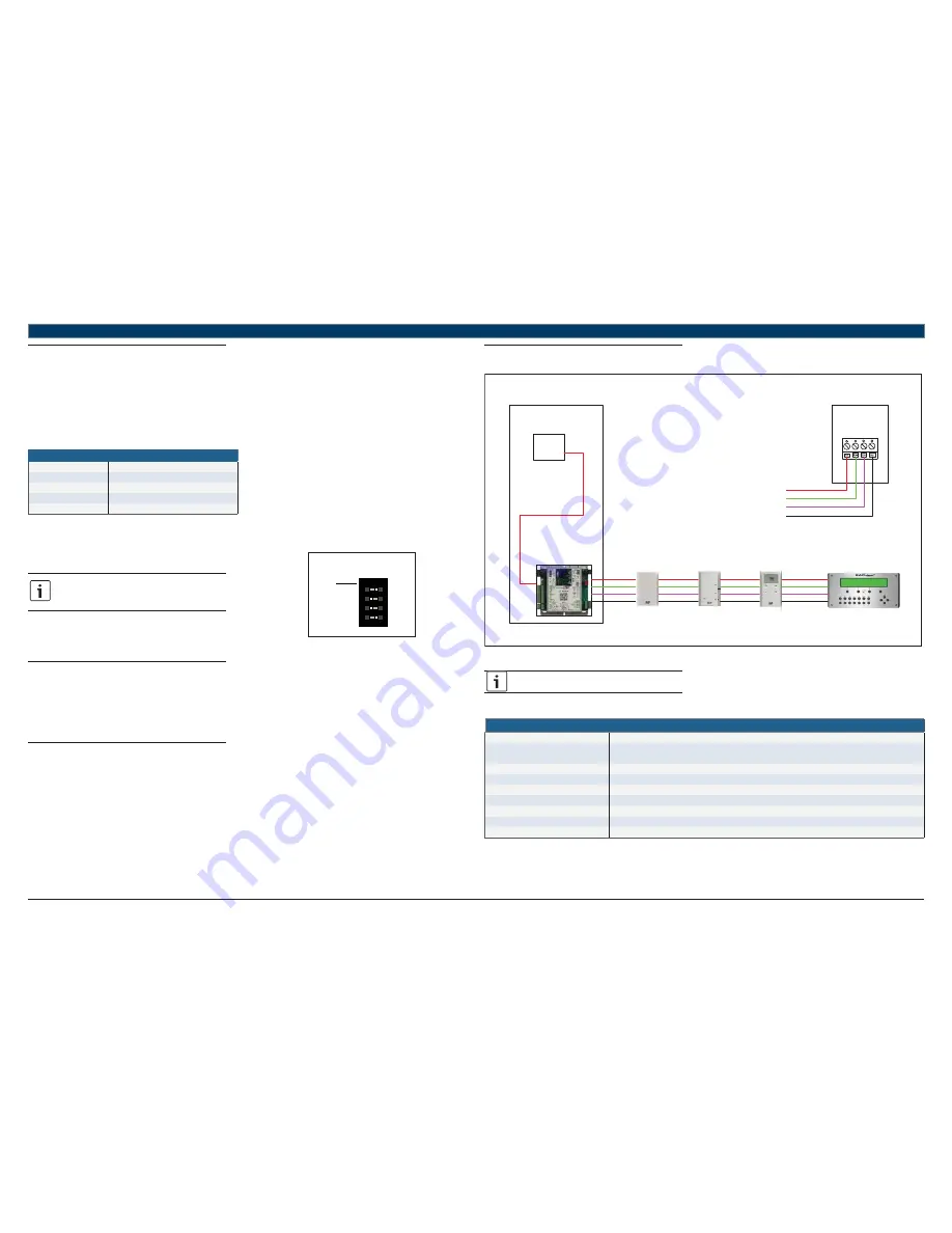
14.8 ZS Sensor Wiring Speci
fi
cation
Red
Green
White
Black
Red
Green
White
Black
Red
Green
White
Black
Red
Green
White
Black
ZS Base
8 mA
ZS Plus
8 mA
ZS Pro with CO2
190 mA
BACview
20 mA
Transformer
Panel
FHP560 Controller
120/220 Vac
24 Vac
Back of ZS Sensor
12 Vdc (red)
Rnet - (green)
Rnet + (white)
GND (black)
Fig. 12 ZS Wiring Diagram
Use the speci
fi
ed type of wire and cable for maximum
signal integrity.
Rnet Wiring Speci
fi
cations
Description
4 conductor, shielded or unshielded, CMP, plenum rated cable
Conductor
22 AWG (7x0096) bare copper if Rnet has only sensors
18 AWG (7x0152) bare copper if Rnet has a BACview® device
Maximum length
500 feet (152 meters)
Insulation
Low-smoke PVC (or equivalent)
Color Code
Black, white, green, red
Shielding
If shielded, Aluminum/Mylar shield (100% coverage) with TC drain wire, terminated at controller
UL temperature rating
32–167°F (0–75°C)
Voltage
300 VAC, power limited
Listing
UL: NEC CL2P, or better
Table 42


