


18 EP Series
Subject to change without prior notice Revised 12-13
8733922168
Dehumidificationselector (Figure #9, item [11]) should
be selected to ‘YES’.
2) Units without optional Hot Gas Reheat, on
dehumidification call, the heat pump fan will operate at a
lower speed to increase dehumidification while cooling.
Dehumidification selector ((Figure #9, item [11]) should
be selected to ‘NO’.
Caution
In this mode, the heat pump will only dehumidify the
space when it is running in cooling mode.
Dehumidification indicator LED (Figure #9, item [4]) will
energize when dehumidification call is present.
To the left of the red and green status LED’s is a row of
1/4” male quick connects. These are used to pass
thermostat inputs on to the rest of the control circuit.
Remember to always turn off unit power at the circuit
breaker before attaching or disconnecting any wiring
from these connections to avoid accidental short circuits
that can damage unit control components.
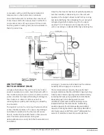
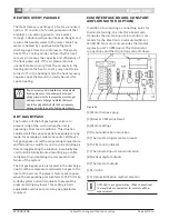
Y1
Y1
POWER
TO PUMP
C
2 DP/ST
RELAYS
POWER SUPPLY
UNIT
TERMINAL
STRIP
(24VAC)
C
FLUID DIFFERENTIAL PRESSURE SWITCH
(DPS)
Pressure/temperature ports are recommended in
both the supply and return lines for system flow
balancing. The water flow can be accurately set by
measuring the water-to-refrigerant heat exchangers
water side pressure drop. See the unit specification
sheets for the water flow and pressure drop
information in the back of this manual.
The discharge water from the heat pump is not
contaminated in any manner and can be disposed of
in various ways depending on local codes (i.e.
discharge well, dry well, storm sewer, drain field,
stream, pond, etc.
When using a single water well to supply both
domestic water and the heat pump care must be taken to
insure that the well can provide sufficient flow for both.
In well water applications a slow closing solenoid valve
must be used to prevent water hammer.
Solenoid valves should be connected across Y and C
on the interface board for all. Make sure that the VA
draw of the valve does not exceed the contact rating
of the thermostat. The function of the differential
switch is to prevent or stop compressor operation
should the water supply fail. This will prevent the unit
from locking out on a safety, requiring a manual reset
to restart.
The switch is piped between the water entering and
leaving connections. Should the pressure drop fall
below set value the switch will open de-energizing the
DPS relay thereby stopping the compressor.
The controller has an adjustment to change the
minimum pressure differential required to open the
switch and may require field adjustment.
The blower operation will not be affected by this
option.
Caution
The start-up process should include checking the
operation of the switch when installed. This
should be done after the system is balanced.
Adjustment should be made if necessary.
Содержание EP015
Страница 1: ...EP Series Installation and Maintenance Manual 8733922168 Revised 12 13 ...
Страница 33: ...33 EP Series 8733922168 Revised 12 13 Subject to change without prior notice Electric Heat Wiring Diagram ...
Страница 34: ...34 EP Series Subject to change without prior notice Revised 12 13 8733922168 Electric Heat Wiring Diagram ...
Страница 38: ...38 EP Series Subject to change without prior notice Revised 12 13 8733922168 ...
Страница 39: ...39 EP Series 8733922168 Revised 12 13 Subject to change without prior notice ...


