


16 EP Series
Subject to change without prior notice Revised 12-13
8733922168
Electric Heat
HEAT RECOVERY PACKAGE
The Heat Recovery package is a factory mounted
option. It consists of a forced pumped unit that
employs a circulating pump to move water
through a double wall/vented heat exchanger and
returns the heated water to the water tank. The
water is heated by superheated refrigerant
discharge gas from the compressor. This waste
heat of the cooling mode captured by the heat
recovery increases the capacity and efficiency of
the heat pump unit. If the air temperature is
uncomfortable coming from the air vents in the
heating mode the heat recovery may need to be
turned off. In the heating mode the heat recovery
captures heat that would normally be used for
space heating.
Caution
If heat recovery unit is installed in an area where
freezing may occur, the unit must be drained
during winter months to prevent heat exchanger
damage. Heat exchanger ruptures that occur
due to freezing will void both the heat recovery
package warranty and the heat pump warranty.
HOT GAS BYPASS
The function of the hot gas bypass valve is to
prevent icing of the air coil when the unit is
operating at low load conditions. This situation
could arise if the space experiences widely varying
loads, for example a conference center. Without a
hot gas bypass circuit the evaporating temperature
will fall and ice could form on the coil restricting air
flow and aggravating the situation. Eventually the
coil could be totally blocked resulting in possible
refrigerant liquid entering the compressor and
failure of the system
The hot gas bypass valve is located in the discharge
line from the compressor and diverts hot gas to the
inlet of the air coil. The valve is factory set to open
when the evaporating pressure falls to 75 PSI for an
R-410A system and will modulate to prevent the
pressure falling any lower. This setting is field
adjustable and this set point may be adjusted as
required.
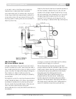
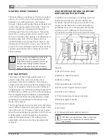
ECM INTERFACE BOARD- CONSTANT
AIRFLOW MOTOR (OPTION)
In addition to providing a connecting point for
thermostat wiring, the interface board also
translates thermostat inputs into control com-
mands for the Electronic Commutated Motor
(ECM) DC fan motor and provides thermostat
signlas to unit’s UPM board. The thermostat
connections and their functions are as follows:
Figure #9
[1] Motor harness plug
[2] Blower CFM adjustment
[3] Motor settings
[4] Dehumidification indication
[5] Thermostat digital contact inputs
[6] CFM count indicator
[7] Thermostat input status indication
[8] Reheat digital outputs
[9] Thermostat outputs
[10] 24 VAC
[11] Dehumidification method selector
Caution
CFM LED is an approximation. Utilize conventional
Test and Balance equipment for accurate airflow
measurement.
Содержание EP015
Страница 1: ...EP Series Installation and Maintenance Manual 8733922168 Revised 12 13 ...
Страница 33: ...33 EP Series 8733922168 Revised 12 13 Subject to change without prior notice Electric Heat Wiring Diagram ...
Страница 34: ...34 EP Series Subject to change without prior notice Revised 12 13 8733922168 Electric Heat Wiring Diagram ...
Страница 38: ...38 EP Series Subject to change without prior notice Revised 12 13 8733922168 ...
Страница 39: ...39 EP Series 8733922168 Revised 12 13 Subject to change without prior notice ...


