


15
EP Series
8733922168
Revised 12-13 Subject to change without prior notice
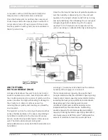
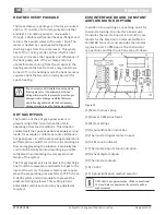
Well Water System
On FHP units’ gas flow to Hot Gas Coils is made
with the increase of DC volts output from Duct
Stat.
8. Check actuator location pin for movement
during modulation. If there is no movement of
pin and the actuator is moving, locate set-screw
and tighten motor body on actuator shaft.
a) To tighten, unscrew set-screw so that it is
loose (use a 3mm metric Allan wrench),
ensure that shaft is all the way to the CCW
position (use a wrench if necessary)
b) Locate clutch release knob (top left of Motor body)
Press knob down, while holding down, rotate turn
knob to full CCW position. Tighten set-screw.
Note:
When the pin is to the right, hot gas
flows to the right (Hot Gas Coil) and if to the
left, hot gas flows to the left (Condenser Coil).
c) An outdoor air low limit switch can be
placed between Transformer and R of the
terminal block to keep the Compressors
from running below 65 degrees entering
outdoor temperature.
d) The factory provided-field installed discharge
air temperature sensor installed by the
contractor in the units discharge air plenum
controls the position of the modulating hot
gas reheat valves to maintain a desired
constant discharge air temperature. This
sensor should be installed at least 10 feet
from the units discharge air outlet to ensure
proper mixing of the leaving air.
e) In situations of low fluid temperature the
amount of hot gas could be limited and the
design leaving air temperature may not be
attained. This can be remedied by the use of
field supplied head pressure controlled
water regulating valves or manually adjusting
the water flow rates accordingly.
Depending on the application in the unoccupied
mode the unit should be disabled through some
type of relay or time clock and the outside air
damper be closed. This will ensure that raw or
unconditioned outside air is not introduced into the
building during the unoccupied mode.
Caution
Control of the hot gas modulation is by the
thermostat in the supply air duct or through the
building management system. A separate
controller is used to control the unit itself.
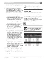
ELECTRIC HEAT
Internally mounted supplemental electric heat
is available on select models of the EP series.
Electric heating elements can operate along
with reverse cycle heating as auxiliary heat or
in lieu of reverse cycle heating (refrigeration
heating) as emergency backup heat.
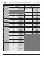
Availability matrix, including available nominal
kW capacities is shown below:
Caution
Internal Eectric Heat cannot be provided with hot
gas reheat. Units with internal Electric Heat must
have 2 field power supplies.
Table 2: Electric Heater Compatibility
tor Only)
Units
5kW
10 kW
15
kW
20
kW
EP018
ü
x
x
x
EP024
ü
ü
x
x
EP030
ü
ü
x
x
EP036
ü
ü
ü
x
EP042
ü
ü
ü
x
EP048
ü
ü
ü
ü
EP060
ü
ü
ü
ü
EP070
ü
ü
ü
ü
Caution
Internal mounted Electric Heat is only available on
top blow vertical cabinets, end blow horizontal
cabinet.
Содержание EP015
Страница 1: ...EP Series Installation and Maintenance Manual 8733922168 Revised 12 13 ...
Страница 33: ...33 EP Series 8733922168 Revised 12 13 Subject to change without prior notice Electric Heat Wiring Diagram ...
Страница 34: ...34 EP Series Subject to change without prior notice Revised 12 13 8733922168 Electric Heat Wiring Diagram ...
Страница 38: ...38 EP Series Subject to change without prior notice Revised 12 13 8733922168 ...
Страница 39: ...39 EP Series 8733922168 Revised 12 13 Subject to change without prior notice ...


