background image

14

en | System overview

DIVAR IP all-in-one 7000 2U

2021.10 | V02 | DOC

Quick installation guide

Bosch Security Systems B.V.

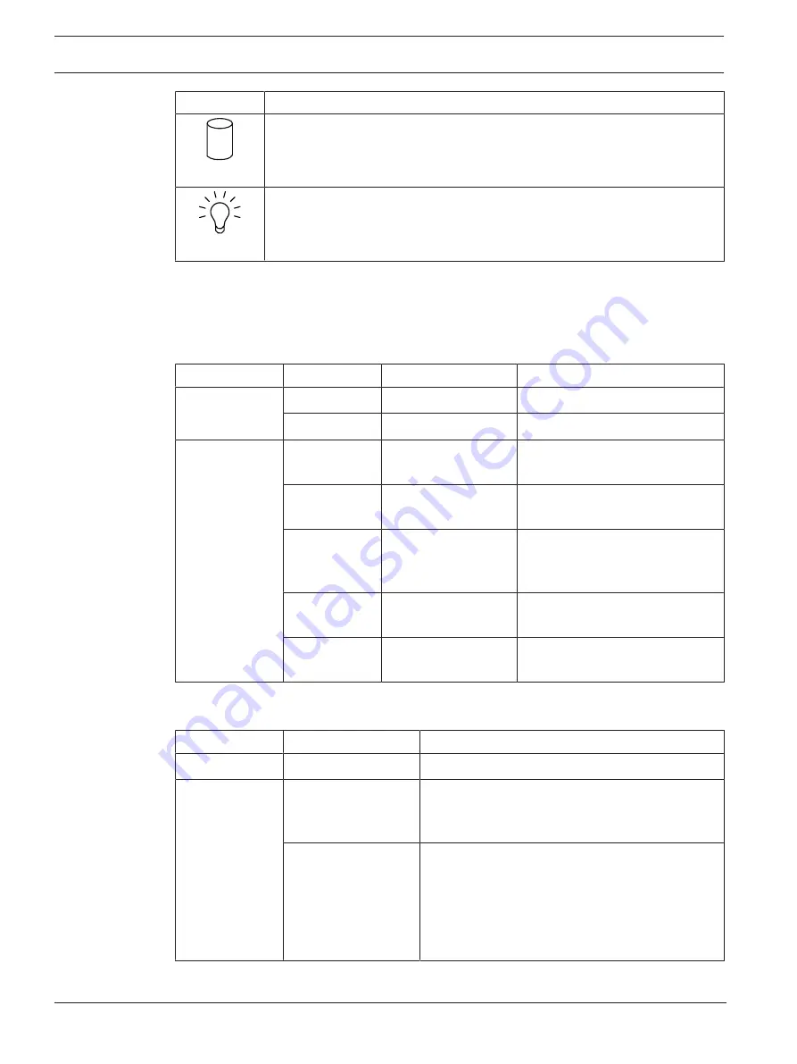
LED

Description

HDD

This LED indicates activity on the HDDs or peripheral drives when flashing.

Power

This LED indicates that power is being supplied to the system's power supply
units.
This LED should normally be illuminated when the system is operating.

Hard drive carrier LEDs

The chassis supports hot-swappable SAS/SATA hard drives in hard drive carriers. Each hard
drive carrier has two LEDs on the front of the carrier: one activity LED and one status LED.
Note: For non-RAID configurations, some LED indications are not supported, for example hot
spare.

LED color

LED state

Description

Activity LED

Blue

Solid On

Hard drive is installed.

Blue

Blinking

I/O activity.

Status LED

Red

Solid On

Failed hard drive with RSTe
support.

Red

Blinking at 1 Hz

Rebuild hard drive with RSTe
support.

Red

Blinking with two
blinks and one stop
at 1 Hz

Hot spare for hard drive with
RSTe support.

Red

On for five seconds,
then off

Power on for hard drive with
RSTe support.

Red

Blinking at 4 Hz

Identify hard drive with RSTe
support.

Power supply LEDs

On the rear of the power supply module, an LED displays the status.

LED color

LED state

Description

Green

Solid On

Power supply is on.

Amber

Solid On

The power supply is plugged in and turned off 
or
The system is off but in an abnormal state.

Blinking

The system power supply temperature has
reached 63 °C.
The system will automatically turn off when the
power supply temperature reaches 70 °C and
restart when the power supply temperature goes
below 60 °C.

Содержание DIP-7380-00N

Страница 1: ...DIVAR IP all in one 7000 2U DIP 7380 00N DIP 7384 8HD DIP 7388 8HD DIP 738C 8HD en Quick installation guide ...

Страница 2: ......

Страница 3: ...al system precautions 15 4 4 Installation considerations 16 5 Rack installation 17 5 1 Separating the sections of the rack rails 17 5 2 Installing the inner rails on the chassis 18 5 3 Installing the outer rails to the rack 18 5 4 Installing the chassis in the rack 19 6 Installing a SATA hard drive 21 6 1 Removing a hard drive carrier from a hard drive bay 21 6 2 Installing a hard drive into a har...

Страница 4: ...do not wear loose clothing such as neckties and unbuttoned shirt sleeves which can come into contact with electrical circuits or be pulled into a cooling fan Remove any jewelry or metal objects from your body which are excellent metal conductors that can create short circuits and harm you if they come into contact with printed circuit boards or areas where power is present After accessing the insi...

Страница 5: ...s Warning Lithium battery Batteries that have been inserted wrongly can cause an explosion Always replace empty batteries with batteries of the same type or a similar type recommended by the manufacturer Handle used batteries carefully Do not damage the battery in any way A damaged battery may release hazardous materials into the environment Dispose of empty batteries according to the manufacturer...

Страница 6: ...f fire or electrical shock do not expose this unit to rain or moisture Never push objects of any kind into this unit through openings as they may touch dangerous voltage points or short out parts that could result in a fire or electrical shock Power supply cords should be routed so that they are not likely to be walked on or pinched by items placed upon or against them playing particular attention...

Страница 7: ...nents Disconnect the power cables before installing or removing any components from the computer including the backplane When disconnecting power you should first turn off the system and then unplug the power cords from all the power supply modules in the system Disconnect the power cable before installing or removing any cables from the backplane When working around exposed electrical circuits an...

Страница 8: ...tic bags until ready for use Touch a grounded metal object before removing the board from the antistatic bag Do not let components or printed circuits boards come into contact with your clothing which may retain a charge even if you are wearing a wrist strap Handle a board by its edges only Do not touch its components peripheral chips memory modules or contacts When handling chips or modules avoid...

Страница 9: ... the unit Information on sales delivery storage and working life period No restrictions or conditions apply for the sale or delivery of this product If stored under the specified conditions the storage period is not restricted If used for the specified purpose in compliance with the safety instructions and technical specifications the working life period of the product is in accordance with normal...

Страница 10: ...unication channels 1 9 Use latest software Before operating the device for the first time make sure that you install the latest applicable release of your software version For consistent functionality compatibility performance and security regularly update the software throughout the operational life of the device Follow the instructions in the product documentation regarding software updates The ...

Страница 11: ...the installation read and follow the safety instructions 2 1 Parts included Make sure that all parts are included and not damaged If the packaging or any parts are damaged contact your shipper If any parts are missing contact your Sales or Customer Service Representative Quantity Component 1 DIVAR IP all in one 7000 2U 1 Rack mount kit 1 Quick installation guide English 1 Registration leaflet 2 Po...

Страница 12: ...upply modules Front view 9 2 6 3 7 4 5 1 8 1 2 USB 2 0 ports 2 Power failure LED 3 Information LED 4 NIC1 and NIC2 LEDs 5 HDD drive activity LED 6 Power LED 7 Reset button 8 Power button 9 Hard drive carrier LEDs Rear view 1 5 9 2 6 3 7 4 8 10 11 1 2 power supply modules 2 2 redundant SSD drives for operating system RAID1 mirror 3 IPMI LAN 4 3 USB ports 3 1 Gen 2 Type A 5 USB port 3 1 Gen 2 Type C...

Страница 13: ...nel LEDs provide status information about the system LED Description Power failure This LED indicates that a power supply module has failed Information This LED indicates the system status System status Description Continuously on and red An overheat condition has occurred This may be caused by cable congestion Blinking red 1 Hz Fan failure check for an inoperative fan Blinking red 0 25 Hz Power f...

Страница 14: ...iption Activity LED Blue Solid On Hard drive is installed Blue Blinking I O activity Status LED Red Solid On Failed hard drive with RSTe support Red Blinking at 1 Hz Rebuild hard drive with RSTe support Red Blinking with two blinks and one stop at 1 Hz Hot spare for hard drive with RSTe support Red On for five seconds then off Power on for hard drive with RSTe support Red Blinking at 4 Hz Identify...

Страница 15: ... your safety Ensure that the leveling jacks on the bottom of the rack are fully extended to the floor with the full weight of the rack resting on them This unit should be mounted at the bottom of the rack if it is the only unit in the rack When mounting this unit in a partially filled rack load the rack from the bottom to the top with the heaviest component at the bottom of the rack In single rack...

Страница 16: ...flow Equipment should be mounted into a rack so that the amount of airflow required for safe operation is not compromised Mechanical loading Equipment should be mounted into a rack so that a hazardous condition does not arise due to uneven mechanical loading Circuit overloading Consideration should be given to the connection of the equipment to the power supply circuitry and the effect that any po...

Страница 17: ... you are using i Notice This rail will fit a rack between 26 and 33 5 deep 5 1 Separating the sections of the rack rails The chassis package includes two rail assemblies in the rack mounting kit Each assembly consists of two sections an inner fixed chassis rail that secures directly to the chassis an outer fixed rack rail that secures directly to the rack itself To separate the inner and outer rai...

Страница 18: ...de of the chassis aligning the hooks of the chassis with the rail extension holes Make sure the extension faces outward just like the pre attached inner rail 2 Slide the extension toward the front of the chassis 3 Secure the chassis with 2 screws as illustrated 4 Repeat steps 1 3 for the other inner rail extension 5 3 Installing the outer rails to the rack Outer rails attach to the rack and hold t...

Страница 19: ...zing mechanism is in place or the rack is bolted to the floor Failure to stabilize the rack can cause the rack to tip over Warning Do not pick up the unit with the front handles The handles are designed to pull the system from a rack only i Notice Mounting the chassis into the rack requires at least two people to support the chassis during installation Please follow safety recommendations printed ...

Страница 20: ... far the chassis will extend out the front of the rack Put larger chassis so that the weight between front and back is balanced If a bezel is included on the chassis remove it 2 Attach one L shaped bracket to each side of the chassis front and one L shaped bracket to each side of the chassis rear 3 Make sure that the brackets are positioned with just enough space to fit the width of the Telco rack...

Страница 21: ...ge 21 2 Installing a hard drive into a hard drive carrier page 21 3 Installing a hard drive carrier into a front drive bay page 23 6 1 Removing a hard drive carrier from a hard drive bay To remove a hard drive carrier from a hard drive bay 1 Press the release button to the right of the hard drive carrier This extends the hard drive carrier handle 2 Use the handle to pull the hard drive carrier out...

Страница 22: ...nting holes in both the hard drive carrier and the hard drive 5 Secure the hard drive to the hard drive carrier with the six screws 1 Hard drive carrier 2 SATA hard drive i Notice Bosch recommends using the respective Bosch hard disk drives The hard disk drives as one of the critical component are carefully selected by Bosch based on available failure rates Hard disk drives not delivered from Bosc...

Страница 23: ...drive carrier into a front drive bay To install a hard drive carrier into a hard drive bay 1 Insert the hard drive carrier horizontally into the hard drive bay orienting the hard drive carrier so that the release button is on the right 2 Push the hard drive carrier into the bay until the handle retracts and the hard drive clicks into the locked position ...

Страница 24: ... B V 7 Turning on the system To turn on the system 1 Plug the power cord from the power supply unit into a high quality power strip that offers protection from electrical noise and power surges Bosch recommends to use an uninterruptible power supply UPS 2 Push the power button on the control panel to turn on the system ...

Страница 25: ... hard drives using the MegaRAID Storage Manager application page 26 8 1 Default settings All DIVAR IP systems are preconfigured with a default IP address and with default iSCSI settings IP Address automatically assigned by DHCP fallback IP address 192 168 0 200 Subnet mask automatically assigned by DHCP fallback subnet mask 255 255 255 0 Default user settings for administrator account User name BV...

Страница 26: ...rage Manager application i Notice The setup process with the MegaRAID Storage Manager application is not necessary for units with pre installed hard drives These units are delivered with a default configuration To configure RAID5 1 Install all hard drives 2 Turn on the system 3 Set up the operating system and install DIVAR IP Software Center as described in the user manual 4 After the DIVAR IP Sof...

Страница 27: ... will be lost This option deletes data on all HDD partitions and overwrites the operating system partition with the factory default image Initial Factory Setup overwriting existing data This option deletes and overwrites data on all HDD partitions Furthermore it overwrites the operating system partition with the factory default image Note This procedure might take very long System Recovery back to...

Страница 28: ...onal documentation and client software For more information software downloads and documentation visit http www boschsecurity com and go to the respective product page in the product catalog You can find the latest software and available upgrade packages in the Download Area of Bosch Security and Safety Systems under https downloadstore boschsecurity com ...

Страница 29: ...DIVAR IP all in one 7000 2U Additional documentation and client software 29 Bosch Security Systems B V Quick installation guide 2021 10 V02 DOC ...

Страница 30: ...30 Additional documentation and client software DIVAR IP all in one 7000 2U 2021 10 V02 DOC Quick installation guide Bosch Security Systems B V ...

Страница 31: ......

Страница 32: ...Bosch Security Systems B V Torenallee 49 5617 BA Eindhoven Netherlands www boschsecurity com Bosch Security Systems B V 2021 202110281645 ...

Отзывы: