background image

70

en | Mechanical installation of Contribution Devices

DICENTIS

2021.01 | V2.2 |

Hardware Installation Manual

Bosch Security Systems B.V.

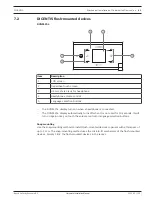
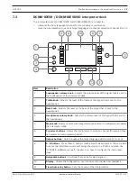
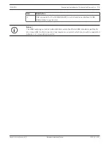
Item

Description

12

Microphone button

 - Enables or disables the microphone. The microphone

button has a red LED that comes on when the microphone is enabled (on-air). A
green LED shows that the booth is not in use.

13

Mute button

 - Temporarily disables the microphone.

Connecting Interpreter desks

Two RJ45 compatible connections for system communication and power are available for
quick and easy connection of the interpreter desks. Loop-through cabling can be applied by
using DICENTIS System cables or star cabling using standard CAT-5e cables and PoE switches.

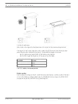
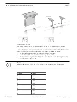
Installing Interpreter desks

The interpreter desks can be installed free-standing or fixed in more permanent installations
(table-top) using mounting screws.

!

Warning!

The screws must be M3 and should not be screwed in deeper than 5 mm (0.2 inches) to avoid
damaging the device.

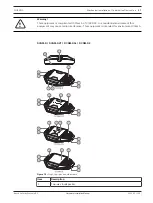
Figure 7.8: 

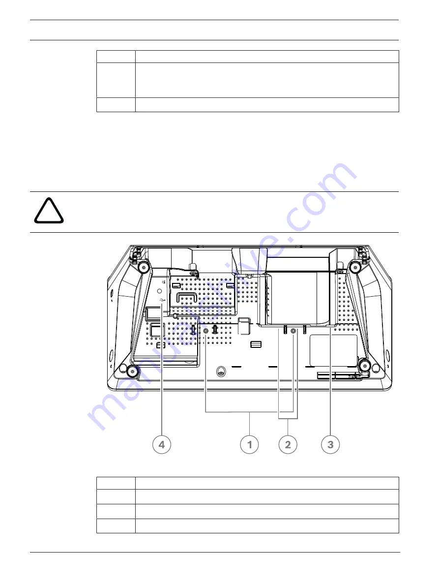
DCNM-IDESK / DCNM-IDESKVID bottom view

Item

Description

1

Screw insert for fixed installation

2

2 x RJ45 connection input/output for system power cable

3

HDMI video output (DCNM-IDESKVID only)

Содержание DCNM-APS2

Страница 1: ...DICENTIS Conference System en Hardware Installation Manual ...

Страница 2: ......

Страница 3: ...oupler to extend a cable 33 5 1 2 Using a cable coupler as a break out box 33 5 1 3 Using a cable coupler as an interface between different types of cable 34 5 1 4 Using a cable coupler to insert power locally 35 5 1 5 Using a cable coupler to switch the system on 36 5 2 DICENTIS System Cable Assemblies 38 5 3 DCNM CBCON Connectors for DICENTIS cable 40 5 4 DCNM CBTK System Network Cable Toolkit 4...

Страница 4: ...nserving resources and in protecting human health and the environment Class A equipment commercial broadcasting equipment This equipment is for professional Class A electromagnetic compatibility equipment Seller or user should pay attention to this point It is intended for use outside the home Warning Changes or modifications made to this equipment not expressly approved by Bosch Security Systems ...

Страница 5: ...g antenna Increase the separation between the equipment and receiver Connect the equipment into an outlet on a circuit different from that to which the receiver is connected Consult the dealer or an experienced radio TV technician for help Note The FCC Wired Class B statement applies to DCNM MMD2 FCC and IC Wireless Statement This device complies with Part 15 of the FCC Rules and with Industry Can...

Страница 6: ...ormation Usually not observing a notice does not result in damage to the equipment or personal injuries Caution The equipment or the property can be damaged or persons can be lightly injured if the alert is not observed Warning The equipment or the property can be seriously damaged or persons can be severely injured if the alert is not observed Danger Not observing the alert can lead to severe inj...

Страница 7: ...5 4 6 1 7 4 8 2015 11 V1 31 5th edition Sections updated 2 4 7 1 Terminology updated 2016 07 V1 4 6th edition Terminology updated DCN multimedia changed to DICENTIS Sections updated 3 1 3 2 4 1 4 3 1 4 3 2 4 4 1 4 4 2 4 4 3 5 3 5 4 7 1 7 2 7 3 7 4 8 2017 10 V1 5 7th edition Terminology and product names updated New section 5 5 Sections updated 5 2 1 5 2 2 7 1 new radio interference warning added 2...

Страница 8: ...rver and 6 3 Dante gateway New section 5 5 5 Using a cable coupler to switch the system on 2019 12 V2 0 12th edition Sections updated 3 2 System extension 4 3 1 Calculation using DCNM APS 2 or DCNM PS 2 6 3 Dante gateway New sections 7 2 DICENTIS Flush mounted devices 7 2 1 DCNM FSL Flush language selector 2020 05 V2 1 13th edition Sections updated 3 System installation overview 7 1 DICENTIS table...

Страница 9: ...r distributing and processing audio video and data signals The DICENTIS Conference System can be quickly and easily configured as a daisy chain configuration or as a star configuration Daisy chain configuration Uses dedicated cabling consisting of CAT 5e cables including two additional power conductors see Typical system setup page 10 Star configuration Each DICENTIS device is connected with an in...

Страница 10: ...ystem 3 Optional video camera Onvif Profile S compatible cameras Sony IP cameras via CGI commands or Panasonic HD Integrated IP external power supply Captures the image of a speaking participant 4 Ethernet switch Ethernet switch with PoE on some ports Routes the system data via Ethernet Provides power to the DICENTIS devices via PoE 5 CAT 5e Ethernet cable minimum requirement 6 Powering switch DCN...

Страница 11: ...ce is used via a Power over Ethernet PoE Ethernet switch Note Only one DICENTIS device should be connected here Participants can use their DICENTIS Discussion device to contribute to a meeting DCNM D DCNM DVT DCNM DSL DCNM DE A typical camera setup in a DICENTIS Conference System consists of Figure 3 2 Typical camera setup 1 H 264 encoder to encode the HD SDI video to H 264 if the video camera is ...

Страница 12: ...01 V2 2 Hardware Installation Manual Bosch Security Systems B V _____ DCNM Cables This system overview does not give information on redundant network options For more information refer to Redundancy options page 28 Refer to Redundancy options page 28 ...

Страница 13: ... Each subnet can have up to 450 DICENTIS nodes Refer to the following table for the node count of DICENTIS equipment The first subnet has 1 DICENTIS Audio processor and powering switch for the audio processing 1 Server PC which hosts the DICENTIS services 1 ARNI Enterprise to increase the size of the system All other subnets have 1 ARNI Standard to increase the size of the system Note There is no ...

Страница 14: ...d subnet masks A subnet is a logical visible subdivision of an IP network The number of DICENTIS devices that can be in the same subnet depends on the subnet mask A standard class C subnet 255 255 255 or 24 can contain 254 IP addresses Some DICENTIS devices have 2 IP addresses For this reason Bosch advises to use 255 255 252 0 or 22 as a subnet mask This allows you to have 1018 IP addresses The fo...

Страница 15: ... switch from influencing the system Each time data hops from one switch to another the age is increased by one This timer can be reached or exceeded because a daisy chain can be used to loop through the DICENTIS devices This timer or restriction cannot be reached when there is no cable redundancy This is because the power limitation will be reached before the max age restriction is reached The tim...

Страница 16: ...aximum of 450 DICENTIS nodes and an OMN ARNIS are connected The system has one OMN ARNIE installed in the first subnet with a maximum of 450 DICENTIS nodes connected Note that only one OMN ARNIE is allowed within a multiple subnet DICENTIS Conference System Subnet four 4 When using multiple subnets make sure that all cameras needed to capture video of the seats are all connected to the same subnet...

Страница 17: ...r consumptions do not exceed the specifications Not doing so will result in malfunctioning at any moment of the DICENTIS Conference System and products 4 1 System capabilities The capability of the DICENTIS Conference System and DICENTIS products depends on The lengths of the system network cables The number of connected devices The system power supply capacity Cable length System network cables D...

Страница 18: ...PoE Ethernet switches Calculation tool The calculation tool can be used to calculate the total power capacity of the system This makes the design and planning of the DICENTIS Conference System easier The calculation tool uses the power consumption of the devices and the system network cable lengths to calculate the needed system power supply capacity The calculation tool is on the DVD supplied wit...

Страница 19: ...vely quiet networks 10 network load it is important to configure your network switches correctly The used QoS is Differentiated Services or DiffServ which is part of the Type of Services field ToS in the IP header For more details on DiffServ IP header see Wikipedia Warning IEEE802 1p is also used for QoS but is limited to layer 2 Since OMNEO uses IP communication this mechanism is not suitable so...

Страница 20: ...nnections to the switch Possibility to create VLANS n a VLAN separation is recommended instead of IGMP snooping because most switches are unable to handle the multicast changes in the system Filtering multicast data may be necessary for some devices such as 100 Mb devices Sony cameras TVOne AMX and others IGMPv3 IGMPv2 snooping in hardware IGMPv3 or IGMPv2 snooping To optimize bandwidth usage IGMP...

Страница 21: ...er Ethernet ports Supports PIM DM or Bidirectional PIM Performs IP routing in hardware i e a layer 3 switch to minimize the routing delay Packet forwarding rate 1 000 000 packets per second per port e g 8 Mpps for an 8 port router Non blocking backplane per switching port i e 2 Gbit per port e g 16 Gbps for an 8 port router MAC address table of at least 1000 addresses per directly connected subnet...

Страница 22: ...t switches If you want to use PoE Ethernet switches continue with chapter Calculation using PoE switches page 25 Refer to Calculation using DCNM APS2 or DCNM PS2 page 22 Installation material and tools page 32 Calculation using PoE switches page 25 4 3 1 Calculation using DCNM APS2 or DCNM PS2 i Notice If you want to use customized cables or a more accurate power supply capacity calculation plan i...

Страница 23: ...5 I 10 71 Tab 4 3 Power consumption Watts i Notice The DCNM FSL is powered by PoE and not via the DCNM APS or DCNM PS See Calculation using PoE switches page 25 for more information Ordering number Cable lengths m ft DCNM CB02 I 2 6 56 DCNM CB05 I 5 16 40 DCNM CB10 I 10 32 81 DCNM CB25 I 25 82 02 Tab 4 4 Cable types and lengths Rear view Figure 4 2 Audio processor and powering switch ...

Страница 24: ...ch and fuse holder 10 Reset button 11 Ground switch grounded or floating 12 Socket 1 without power 13 Socket 2 low power 15 17 19 Socket 3 4 5 high power 14 16 18 20 Overload LED for sockets 2 5 Green Power OK Red Overload Remove cable and wait a few seconds for the system to reset the overload Network and Power connector Max power output W Max devices Socket 1 12 No power capacity Socket 2 13 15 ...

Страница 25: ...r consumption of the cable does not need to be counted if only one device is connected to this output 2 The shortest redundant cable does not need to be counted Refer to Calculation using PoE switches page 25 4 3 2 Calculation using PoE switches Select one or more PoE Ethernet switches to supply power to the DICENTIS devices Each DICENTIS device must be connected to an individual PoE enabled outpu...

Страница 26: ...ation Manual Bosch Security Systems B V Figure 4 4 Bottom view DICENTIS devices DCNM MMD DCNM MMD2 Figure 4 5 Bottom view DICENTIS devices DCNM D DCNM DVT DCNM DSL DCNM DE Figure 4 6 Bottom view DICENTIS Interpreter devices DCNM IDESK DCNM IDESKVID Item Description 1 Network connector ...

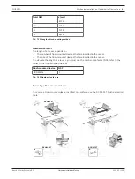
Страница 27: ...DICENTIS System installation design and planning en 27 Bosch Security Systems B V Hardware Installation Manual 2021 01 V2 2 Item Description 2 Network PoE connector ...

Страница 28: ... explain the redundancy options that can be used when designing your DICENTIS Conference System Each option can be combined in the DICENTIS Conference System providing you observe the redundant cabling limitations Refer to Redundant cabling for DCNM APS2 DCNM PS2 units page 29 Redundant server PC page 31 i Notice Rapid Spanning Tree Protocol RSTP must be enabled in the DICENTIS Conference System f...

Страница 29: ...ber of devices in the loop The grey line shows the largest loop The sign shows the way the devices are counted In the example below up to 19 22 3 19 discussion devices can be connected 1 1 2 Figure 4 7 DICENTIS discussion devices connected with redundant cabling between DCNM PS2 DCNM APS2 type units 1 DICENTIS system 2 Network switch with optional redundant power supply 3 DCNM APS2 4 DCNM PS2 5 DI...

Страница 30: ...power socket 3 on one unit can be connected to high power socket 4 on another unit Note The redundant loop must be connected to another DCNM PS2 type unit You cannot use DCNM PS DCNM APS type units to create redundant loops for power You can create a redundant loop for signal only by connecting the DICENTIS devices in a daisy chain configuration to the same DCNM PS2 or DCNM APS2 although this is n...

Страница 31: ...f the loop cable also consumes power The figure shows how to calculate the number of devices in the loop The grey line shows the largest loop The sign shows the way the devices are counted In the example below up to 17 22 5 17 devices can be connected Figure 4 8 Redundant DICENTIS server PC with redundant components and cables 1 DICENTIS system 2 Network switch with optional redundant power supply...

Страница 32: ...em network cables DCNM CBxxx The minimum bend radius of the system network cable is a 35 mm radius 5 1 DCNM CBCPLR Cable couplers Cable couplers can be used to extend cables in a floor pod as break out box as an interface between DICENTIS cable and standard CAT 5E cable combined with a separate power cable to insert power locally to the participant devices to switch the system on by using two cabl...

Страница 33: ...r example three 25 m DCNM CB25 I cables together to form a 75 m cable Note The cable length is not allowed to exceed 100 m No more than 2 cable couplers can be used in one trunk 5 1 2 Using a cable coupler as a break out box The DICENTIS Cable coupler can be used in a floor pod as a break out box for example if you want to connect temporary devices like a rostrum microphone The cable coupler can b...

Страница 34: ...cabling coming from the technical room has to be connected with DICENTIS cable in the conference room To set this up 1 Open the housing of the cable coupler 2 Connect the power cables to the screw terminals and 3 Remove the break out of the housing to guide the power cables through 4 Create a tension release Warning Risk of electric shock Exposed power cables are a potential hazard Make sure all p...

Страница 35: ...be used to insert a local power supply enabling you to place a third party 48 VDC power close to the participant devices To set this up 1 Open the housing of the cable coupler 2 Connect the power cables to the screw terminals and 3 Remove the break out of the housing to guide the power cables through 4 Create a tension release Warning Risk of electric shock Exposed power cables are a potential haz...

Страница 36: ...om 4 3 to 5 0 A When the power supply has an automatic restart after a short circuit this restart function should have an interval time of 3 to 4 seconds and should have no more than 4 restart attempts Upon powering off the power supply the output should be less than 9 V 1 mA The maximum distance between the A PS and the conference device is limited to 100 m due to the Ethernet properties P Figure...

Страница 37: ...upler which is connected to output 3 of the A PS 3 Remove the break out of the housing to guide the power cables through 4 Connect the wires according the figure below 5 Create a tension release Warning Risk of electric shock Exposed power cables are a potential hazard Make sure all power cables are securely fastened by fixing them with a tie wrap on the inside of the box see drawing Creating a te...

Страница 38: ...s of the A PS are enabled and any devices connected to these outputs are also powered up 3 Relay R1 has a timer of 1 minute so the switch will stay closed for 1 minute after releasing switch S1 or powering down the system 4 When the high power trunks are powered up the switch of relay R2 will power relay 1 to keep the switch closed 5 2 DICENTIS System Cable Assemblies The DICENTIS System Cable Ass...

Страница 39: ... 39 Bosch Security Systems B V Hardware Installation Manual 2021 01 V2 2 Ordering number Cable lengths DCNM CB05 I 5 16 40 DCNM CB10 I 10 32 81 DCNM CB25 I 25 82 02 Tab 5 6 Cable types and lengths Figure 5 9 DCNM CBxx I cable and connector view ...

Страница 40: ...CNM CB250 as well as stranded core cable DCNM CB02 DCNM CB05 DCNMCB10 DCNM CB25 DCNM CB02B DCNM CB05B DCNM CB10B DCNM CB25B DCNM CB250B 1 1 3 4 6 7 9 8 5 2 3 4 5 7 9 8 6 Figure 5 10 DCNM CBCON Front and exploded view Item Description 1 Strain relief boot 2 Ferrule 3 Plug connector shield 4 Power contacts Qty 2 5 Load bar 6 Power contact cavity 2 places 7 Housing 8 Locking latch 9 Signal contact ca...

Страница 41: ...CNM CB250 I System Installation Cable page 42 or DICENTIS System Cable Assemblies page 38 Item Description 1 Power wiring tool 2 Signal wiring tool Tab 5 7 Toolkit content i Notice Please consult the custom length for system network cables section on the DVD which can be downloaded at https licensing boschsecurity com software Refer to DICENTIS System Cable Assemblies page 38 DCNM CBCON Connectors...

Страница 42: ...n system network cable Refer also to the sections DCNM CBCON Connectors for DICENTIS cable page 40 and DCNM CBTK System Network Cable Toolkit page 41 i Notice The maximum system network cable length is 100 m 328 9 ft i Notice Please consult the custom length for system network cables section on the DVD which can be downloaded at https licensing boschsecurity com software Refer to DCNM CBCON Connec...

Страница 43: ...l a booth on air indicator outside the booth to display on the Interpreter desk that the telephone system outside the booth is ringing and to display on the Interpreter desk that a sensor inside the booth detects a too high CO2 level Figure 5 11 Interpreter s booth Description of the device Figure 5 12 DCNM IDESKINT 1 USB B connector Connects the device to the DCNM IDESK s USB A input 2 8 pin Phoe...

Страница 44: ...recess 4 to prevent side movement C B A Figure 5 13 Screw max dimensions Flat head A 8 mm B 2 mm C 2 5 mm Connection USB B to USB A The interface is connected to the USB A port of one of the DCNM IDESK devices inside the interpreter s booth The maximum length of the USB cable is 5 m Note the USB cable must be purchased separately 8 pin Phoenix connector The 8 pin Phoenix connector interfaces with ...

Страница 45: ...NPUT Positive Tab 5 8 Connector pinout Note the female plug to be used with the 8 pin connector is supplied pre assembled with the product You will need to make the wire connections which only require simple push in action to lock Wiring The connection to the Phoenix connector has to be made using ferrules The tables below give more details on the connection Conductor cross section max solid and f...

Страница 46: ...46 en Installation material and tools DICENTIS 2021 01 V2 2 Hardware Installation Manual Bosch Security Systems B V Figure 5 15 Connection diagram ...

Страница 47: ...NM DE DCNM MMD DCNM MMD2 The Powering switch is used to supply power to devices Scope of delivery The Audio processor and powering switch and Powering switch are shipped with the following parts 1x Mains power cord 1x Safety instructions 1x Set of 19 inch mounting brackets 4x bottom feet 1x DVD containing manuals only with Audio processor and powering switch Front view Figure 6 1 Audio processor a...

Страница 48: ...essor and powering switch Figure 6 3 Powering switch Item Description 1 5 XLR line outputs 1 and 2 2 6 RCA line outputs 1 and 2 3 7 XLR line inputs 1 and 2 4 8 RCA line inputs 1 and 2 9 Mains inlet mains switch and fuse holder 10 Reset button 11 Ground switch grounded or floating 12 Socket 1 without power 13 Socket 2 low power 15 17 19 Socket 3 4 5 high power ...

Страница 49: ... Equipment en 49 Bosch Security Systems B V Hardware Installation Manual 2021 01 V2 2 Item Description 14 16 18 20 Overload LED for sockets 2 5 Green Power OK Red Overload Remove cable and wait a few seconds for the system to reset the overload ...

Страница 50: ... are supplied with the Audio processor and powering switch and Powering switch Refer to the following illustration 4 Connect all required cabling 4 Connect the mains supply Figure 6 4 19 inch rack flat surface and feet mounting Item Description 1 19 inch rack mounting bracket 2 Flat surface mounting bracket 3 Feet mounting i Notice The unit extends 30 mm in front of the 19 mounting brackets when i...

Страница 51: ...ications i Notice The DICENTIS System server contains a printed Microsoft End User License Agreement EULA that needs to be handed over to the End User i Notice Mounting accessories are available from HP Figure 6 5 DCNM SERVER connections Item Description 1 Network port to connect the DICENTIS system 2 Power supply input 3 Network port to connect the DCNM SERVER to a network other than the DICENTIS...

Страница 52: ...gners to take advantage of these unique OMNEO features and manage their network configurations with additional multicast management and RSTP network topologies when combining OMNEO and standard Dante networks The OMN DANTEGTW features Audio streams 64 in both directions Sampling rate 48 kHz Audio 24 bit Audio encryption 16 streams in both directions Mechanical Mounting Mounted in a 19 rack Dimensi...

Страница 53: ...n 2 Dante connection 3 Power input 24 48 VDC 10 W optional 4 Power supply 5 OMNEO connection 6 Reset recessed button 7 Power LED Network port LED color Description Green 1 Gbit s connection Blinking indicates activity traffic Preferred connection Orange 100 Mbit s connection Blinking indicates activity traffic Supported connection not preferred Off No connection or 10 Mbit s connection Connection ...

Страница 54: ...thernet connector must show the link indication If there are multiple Dante gateway s in the same OMNEO network make sure the DanteTM side of these gateways is also in the same DanteTM network Make sure there is no network connection between the DanteTM and the OMNEO side This is never allowed If there is only a single Dante gateway use the Dante controller to set the Dante gateway as preferred cl...

Страница 55: ...ernet connector LEDs If they are lighted power cycle the Dante gateway to restart it If the Ethernet LEDs are off the power supply is probably broken and needs to be exchanged How to install To install the Dante gateway 4 Connect the Dante network port in the OMN DANTEGTW to a network port in the Dante network 4 Connect the OMNEO network port in the OMN DANTEGTW to the OMNEO network 4 Connect the ...

Страница 56: ...NTIS tabletop devices DCNM MMD DCNM MMD2 Figure 7 1 Front top rear and side views Item Description 1 7 capacitive touch screen 2 LED strip 3 Two way loudspeaker 4 3 5 mm stereo jack for headphone or headset with integrated microphone 5 Headphone volume control 6 Microphone request button 7 Chairperson priority or microphone mute button 8 Near Field Communication NFC reader DCNM MMD2 only 9 Cable g...

Страница 57: ...nual 2021 01 V2 2 Warning This equipment is compliant with Class A of CISPR 32 In a residential environment this equipment may cause radio interference This equipment is intended for environment Class A DCNM D DCNM DVT DCNM DSL DCNM DE Figure 7 2 Front top rear and side views Item Description 1 Two way loudspeaker ...

Страница 58: ...crophone request button for second participant 4 Microphone request button 5 Voting buttons 6 Language selection buttons 7 Language display 8 4 3 capacitive touch screen 9 3 5 mm stereo jack for headphone 10 Headphone volume control 11 Microphone input connector 12 Cable guides DCNM DE DCNM DVT and DCNM DSL are compliant with the Radio Equipment Directive RED 2014 53 EU Operating frequency is 13 5...

Страница 59: ...over Ethernet is used DICENTIS devices cannot be daisy chained The star configuration makes use of connectors underneath the devices ensuring for a neat tidy system installation especially advantageous for TV coverage To connect the system network cables to the DICENTIS devices refer to the following figure 1 Insert the system network cable connector 2 2 Lead the system network cable through the c...

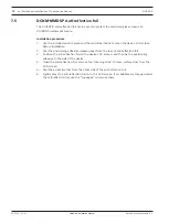
Страница 60: ...4 Bottom view DICENTIS devices DCNM D DCNM DVT DCNM DSL DCNM DE Item Description 1 Screw insert for fixed installation 2 2x RJ45 connection input output for system power cable 3 Cable guides 4 USB connector for future use DCNM MMD DCNM MMD2 only Refer to DICENTIS System Cable Assemblies page 38 DCNM CB250 I System Installation Cable page 42 ...

Страница 61: ...age selection buttons The DCNM FSL display turns on when a headphone is connected The DCNM FSL display automatically turns off when it is not used for 10 seconds It will turn on again once you touch the volume control or language selection buttons Snap mounting Use the snap mounting method to install flush mounted devices in panels with a thickness of up to 2 mm The snap mounting method uses the c...

Страница 62: ... factor NSF of the flush mounted device that must be installed in the recess To calculate the length of a recess Get the number size factor NSF of the flush mounted device Use the NSF to get the length x of the recess from the table Total NSF x mm 1 38 2 2 88 2 Tab 7 11 Lengths snap mounting method Block mounting Use the block mounting method to install flush mounted devices in surfaces with a thi...

Страница 63: ...DICENTIS Mechanical installation of Contribution Devices en 63 Bosch Security Systems B V Hardware Installation Manual 2021 01 V2 2 T8 121 5mm 0 5 R2 5 0 5 0 5 2mm 33º 1 x2 DCN FPT 2 x2 3 x2 T8 2 1 4 x2 ...

Страница 64: ...or NSF of the flush mounted devices that must be installed in the recess To calculate the length of a recess 1 For each flush mounted device get the number size factor NSF 2 Add the NSFs of the flush mounted devices to get the total NSF 3 Use the total NSF to get the length x of the recess from the table The length includes the DCN FCOUP couple pieces i Notice Install DCNM FEC Flush end caps on th...

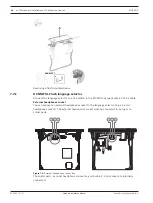
Страница 65: ...ush mounted devices that are installed in the recess The size of the flush mounted devices that are installed in the recess To calculate the length of a recess you must use the number size factor NSF refer to the table of the flush mounted devices Flush mounted device NSF DCNM FSL 2 Tab 7 13 Number size factors Removing a flush mounted device To remove a flush mounted device installed on a surface...

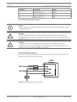
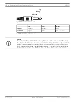
Страница 66: ... selector to a PoE switch in the DICENTIS network with a CAT 5e cable External headphones socket You can connect an external headphones socket to the language selector e g a 3 5 mm headphones socket The external headphones socket must be connected to a plug or to solder pads EXTERNAL HEADPHONE S1540 Figure 7 5 External headphones connection The solder pads external headphone connector and built in...

Страница 67: ...CNM FSL make sure that all connections are electrically floating In case any connections are part of an earth loop unexpected system behavior can occur Warning To prevent the user from suffering an unpleasant ESD discharge while inserting the headphones into the connector always use a headphone connector with a plastic front in combination with the external headphone connection External headphone ...

Страница 68: ...e jack connection i Notice The jack connector must include internal plug detection which is used to enable the display The display will not turn on if you use an incorrect connector it should have a jack inserted switch If you do not want to use this function you must connect the detect signal to GND so that the device thinks that a headphone is connected Please note that this will cause the butto...

Страница 69: ...bass of the signal that is sent to the headphones 4 Headphones volume knob Adjusts the volume level of the signal that is sent to the headphones 5 Menu knob Rotary control with integrated push button to configure and operate the interpreter desk 6 Pre select buttons Allows the interpreters to select a channel from which they can render an interpretation input 7 Output buttons Sets the output the t...

Страница 70: ...and power are available for quick and easy connection of the interpreter desks Loop through cabling can be applied by using DICENTIS System cables or star cabling using standard CAT 5e cables and PoE switches Installing Interpreter desks The interpreter desks can be installed free standing or fixed in more permanent installations table top using mounting screws Warning The screws must be M3 and sh...

Страница 71: ...tem Description 4 USB connector for the DCNM IDESKINT On air telephone interface DCNM IDESK Refer to section 5 6 i Notice The HDMI outgoing current is limited at 60mA while the official HDMI standard specifies 55 mA Some HDMI to VGA converters may require more current which may result in unexpected behavior or a non working converter ...

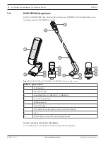
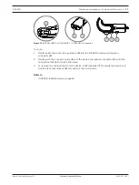
Страница 72: ...ith the DICENTIS devices Figure 7 9 DCNM HDMIC and DCNM MICS DCNM MICL front and bottom view Number Description 1 LED indicator 2 Microphone grill 3 Adjustable stem DCNM MICS DCNM MICL 4 Connection guidance 5 Slider guidance 6 Connector plug 7 Lock slider for lock release Press and shift to release 8 Lock 9 Device female connector see following figure How to connect or remove the microphone The mi...

Страница 73: ... 1 Gently guide the connection guidance 4 into the DICENTIS device microphone connector 9 2 Gently push the connector plug 6 into the device microphone connector 9 until the connection lock 5 fits click into place 3 To remove the microphone from the device Shift lockslider 7 towards the device and hold in place lock release 8 and pull out the microphone Refer to DICENTIS tabletop devices page 56 ...

Страница 74: ...e device LCD screen before installation 2 Peel the positioning adhesive release paper from the rear of anti reflection foil 3 Position the anti reflection foil on the device LCD screen and then fix the positioning adhesive to the side of the device 4 Open the anti reflection foil and use the cleaning stick to clean surface dust from the LCD screen 5 Peel the protective film from the other side of ...

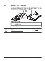
Страница 75: ...rmanently display the participant s name on the rear of a DICENTIS multimedia Device The name card holder has two magnets 2 that allow it to be easily attached to and removed from the rear of the device Figure 7 11 DCNM NCH assembly Item Description 1 Name card holder 2 Magnets i Notice A paper insert template is included on the DVD that can be downloaded at https licensing boschsecurity com softw...

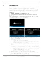
Страница 76: ...zes 1 After the DICENTIS multimedia Device the DICENTIS discussion Extended have initialized the diagnostic screen is shown 2 If the text Link down is shown The network cable is not connected or defective The device is only connected with one system network cable Link down is shown on the side where the device is not connected 3 If the system network cable is correctly connected to the network the...

Страница 77: ...Manual 2021 01 V2 2 Downloading devices is not covered in this manual Refer to the DICENTIS configuration manual on how to download the devices Customer service If a fault cannot be resolved please contact your supplier or system integrator or go directly to your Bosch representative ...

Страница 78: ...78 Installation Test DICENTIS 2021 01 V2 2 Hardware Installation Manual Bosch Security Systems B V ...

Страница 79: ......

Страница 80: ...Bosch Security Systems B V Torenallee 49 5617 BA Eindhoven Netherlands www boschsecurity com Bosch Security Systems B V 2021 202102021655 ...

Отзывы: