background image

D7050DH 

|


Installation Instructions | 3.0 

Wiring the D343 


Bosch Security Systems, Inc. | 9/06 | 49325E 


3.0  Wiring the D343 

You can wire the D343 in series as shown in 

Figure 2


Figure 2: 

Wiring the D343 Duct Housing 

(-)

Tamper
Disable

Reset

Disable

1 4   1 3   1 2   11   1 0     9

1
2
3
4
5
6
7
8

B

B

R

L

R

E

K

N

D

B
L
U

G
R
N

Y
E
L

O
R
N

Tamper
Disable

Reset

Disable

1 4   1 3   1 2   11   1 0     9

1
2
3
4
5
6
7
8

B

B

R

L

R

E

K

N

D

B
L
U

G
R
N

Y
E
L

O
R
N

(+)

1

2

1 -  Input output module for the D7039 or DS9431 

2 -  Multiplex bus connections 


4.0  Setting the Address 


Set the D7050DH address before 
connecting to the control panel and 
applying power. The address number is the 
same as the input point or zone number. 

Set the D7050DH’s address using a flat-blade 
screwdriver to position the rotary switches  
(

Figure 3

) located on the back. Note that the switches 

click when turned. 

The valid address range is from 009 to 255. Refer to 
the 

D7024 Operation and Installation Guide

 (P/N: 31499) 

or the 

DS9400M Reference Guide 

(P/N: 44578) for 

additional address limitations. 


Figure 3: 

Setting the D7050DH Address 

0

5

1

2

3

4

6

7

8

9

0

5

1

2

3

4

6

7

8

9

0

2

1

2

0

1

A

B

1

2

3

1 -  Hundreds        2 -    Tens           3 -    Ones 


A = D7024 FACP, B = DS9400 FACP 

For example: 


0 hundreds, 9 tens, 5 ones = Address 95 on       


  the D7024 FACP 


The A address range works on the D7039 
Multiplex Expansion Module with the 
D7024 FACP. The B address range works 
on the DS9431 Multiplex Expansion 
Module with the DS9400M FACP. 

Figure 3

 shows the A address range set at 095, allowing 

the D7039 to work with the D7024 FACP.


5.0 Mounting 

1.


Remove the tamper screw located in the recess  
on the top of the dust cover.  

2.


Remove the dust cover.  

3.


Mount and wire the duct housing according to the 

D343 Installation Instructions

 (P/N: 48199). 

4.


Mount the D7050DH to the base by turning it 
clockwise until it clicks into place (

Figure 4

). 


Figure 4: 

Mounting the D7050DH on the Base 

+1

R2

3-

1

2

2


1 -  Base contacts (three sets) 

2 -  Set detector contact here and rotate clockwise 


The detector is keyed. Do not force the 
detector onto the base. 


Содержание D7050DH

Страница 1: ...EN Installation Instructions Multiplex Photoelectric Duct Smoke Detector D7050DH ...

Страница 2: ...n The D7050DH Figure 1 is Underwriters Laboratories Inc UL Listed and requires a D343 Duct Detector Housing Use this detector with the D7024 or a DS9400M that includes a D7039 or DS9431 Multiplex Expansion Module An LED indicator on the head flashes every 3 to 8 sec to ensure the D7050DH has power and the smoke sampling circuitry functions This LED flashes at least once each second during an alarm...

Страница 3: ...ation and Installation Guide P N 31499 or the DS9400M Reference Guide P N 44578 for additional address limitations Figure 3 Setting the D7050DH Address 0 5 1 2 3 4 6 7 8 9 0 5 1 2 3 4 6 7 8 9 0 2 1 2 0 1 A B 1 2 3 1 Hundreds 2 Tens 3 Ones A D7024 FACP B DS9400 FACP For example 0 hundreds 9 tens 5 ones Address 95 on the D7024 FACP The A address range works on the D7039 Multiplex Expansion Module wi...

Страница 4: ...g to the next detector 7 2 Sensitivity Testing Calibration is important in determining a detector s continued operation Depending on local regulations calibration testing might be required more than once a year According to NFPA72 perform a Calibration Test at installation and every other year thereafter Perform a Functional Test monthly Test the D7050DH s sensitivity to meet NFPA 72 requirements ...

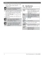
Страница 5: ...red by the voltmeter is half the sensitivity in ft obscuration of the D7050DH b Multiply the voltage by 2 The result must be within the factory marked calibration range printed on the label located on the bottom of the D7050DH c If the D7050DH is outside the factory marked calibration range remove it and clean it Or replace it as described in Section 7 1 Operational Testing d After cleaning rechec...

Страница 6: ...ion Refer to Section 7 0 Testing beginning on page 4 Do not paint the D7050DH Paint or other foreign matter covering the screens can stop or delay smoke from entering the detector 9 0 Specifications Table 3 column width table Standby Current Refer to the D343 Installation Instructions P N 48199 the DS9400M Reference Guide P N 44578 and the DS6431 Installation Instructions P N 41381 Alarm Current R...

Страница 7: ...D7050DH Installation Instructions Bosch Security Systems Inc 9 06 49325E 7 Notes ...

Страница 8: ... 2006 Bosch Security Systems Inc 49325E Bosch Security Systems Inc 130 Perinton Parkway Fairport NY 14450 9199 Customer Service 800 289 0096 Technical Support 888 886 6189 ...

Отзывы: