1 689 989 212
2014-10-31
|
Robert Bosch GmbH
16 | 1 687 010 496 | Preparation for testing
en
4. Preparation for testing
4.1
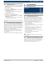
Clamping the CB 28
i
A general description is provided. You will obtain
further information about handling the clamping
components and multi-plate clutches required to
clamp pumps from the appropriate product instruc-
tions in the Bosch ESI[tronic].
!
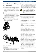
Before you clamp the CB 28 (fig. 2, item 6) pump on
the EPS, check the ease of movement of the pump
drive shaft and check the pump housing for cracks.
Pumps on which the drive shaft does not move freely
or is blocked, or with the housing cracked may not
be clamped and tested.
!
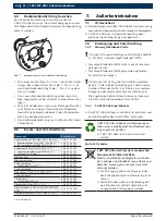
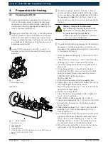
Ensure that the housing O-ring (fig. 1, item 1) is
mounted on the CB 28 (also see ESI[tronic] spare
parts list).
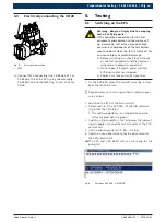
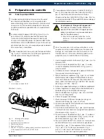
1
Fig. 1:
CB 28
1 CB 28 flange O-ring
Procedure:
458897-10_Le
1
2
3
4
5
6
Fig. 2:
Pump clamping
1 Protective hood
2 Drive coupling
3 Coupling half
4 Clamping bracket
5 Clamping flange with
4 blind holes for storing the 4 hexagon
bolts (4 x M10 x 30 ISO 4017-8.8)
6 CB 28
i
The drive coupling 1 686 401 026 (fig. 2, item 2)
and the protective hood 1 685 510 148 (fig. 2, item
1) are included in the scope of delivery of EPS 815.
The angle plate 1 688 010 129 (fig. 2, item 4) is a
special accessory for EPS and must be procured for
the test.
Warning - danger of entanglement!
Due to rotating or moving parts when the
drive motor is running, body parts or cloth-
ing could be caught and pulled in.
Mount the protective hood at a distance
of < 5 cm from the flywheel.
i
The permissible tightening torques for the clamping
components, multi-plate clutches, and hoses are
provided in the appropriate product test instructions
in the Bosch ESI[tronic].
1.
Attach the drive coupling (fig. 2, item 2) to the EPS
flywheel.
2.
Slide protective hood (fig. 2, item 1) over the drive
coupling (fig. 2, item 2) and up to the flywheel.
3.
Insert disk spring of the CB 28 in the groove of the
drive shaft.
4.
Fit coupling half (fig. 2, item 3) onto the drive
shaft of the CB 28 in such a manner that the disk
spring is covered. Brace using mounting wrench
1 687 951 030. Tightening torque =
160 Nm –165 Nm.
5.
Fit the mounting sleeve onto the coupling half.
6.
Apply a light coating of oil to the radial shaft seal of
the fixing flange and mounting sleeve.
7.
Mount the fixing flange (fig. 2, item 5) to the CB 28
using the 4 hexagon bolts.
8.
Remove mounting sleeve.
9.
Place CB 28 with fixing flange into the angle plate
(fig. 2, item 4) and fasten.
10.
Slide CB 28 onto drive coupling (fig. 2, item 2).
11.
Clamp the coupling half (fig. 2, item 3) on the CB 28
between the clamping jaws of the drive coupling
(fig. 2, item 2).
12.
Slide protective hood (fig. 2, item 1) over the drive
coupling (fig. 2, item 2) and coupling half (fig. 2,
item 3) and fasten.
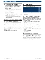
13.
Turn flywheel of EPS by hand and ensure that grind-
ing noises do not occur between protective hood
(fig. 2, item 1), drive coupling (fig. 2, item 2), and
coupling half (fig. 2, item 3). If grinding noises oc-
cur, correct the seat of the protective hood.
14.
Attach the angle plate (fig. 2, item 4) to the clamp-
ing bracket using the two fastening screws.
Содержание CB 28
Страница 2: ......


