background image

6720818454 (2016/02) US

SSB 

24 | Installation

• 

Remodeling areas;

• 

Garages with workshops.

4 .7 .1 

General venting and combustion air piping system

The SSB boilers require an approved vent system-designed for positive 

pressure.

Vent connectors serving appliances vented by natural draft shall not be 

connected to any portion of mechanical draft systems operating under 

positive pressure.

Ensure that the flue pipes and seals are not damaged.

Use only primer and glue compounds approved for use with the vent 

material used.

Never install a barometric or a thermally controlled vent damper with this boiler.

Do not route the flue system piping through or inside another duct that is 

used for exhausting air or other flue gases.

The condensate trap must be primed at all times. Failure to do so may 

allow combustion gases to escape into boiler room.

The unit is to be used for either direct vent installation or for installation 

using room air for combustion. When room air is used, it is necessary to 

provide an adequate opening for the fresh air intake.

You must use any of the vent/air piping methods shown in this manual.

Be sure to locate the unit such that the vent and combustion air piping 

can be routed through the building and properly terminated. 

The boiler / vent installation must be in accordance with Venting 

of Appliances, of the latest edition of the National Fuel Gas Code, 

ANSI Z223.1/NFPA 54 or section, Venting Systems and Air Supply 

for Appliances, of the CAN/CSA B149.1, Natural Gas and Propane 

Installation code or applicable provisions of the local, state and federal 

building codes.

All vent pipes must be installed according to the vent manufacturer’s 

instructions.

The exhaust vent and the combustion air inlet lines must be supported to 

prevent sagging per the vent manufacturer’s instructions. 

Do not mix components from different systems. The vent system could 

fail, causing leakage of flue products into the living space. Use only 

approved materials.

Use of cellular core PVC and CPVC for venting system is not allowed.

a

a

WARNING: Improper venting due to failure to comply with 

the warnings above can result in excessive levels of carbon 

monoxide!

The exhaust pipe must be pitched a minimum of a 1/4 inch per foot back 

to the boiler (to allow drainage of condensate).

The vent system shall be installed so as to prevent the accumulation of 

condensate.

Consult local and state codes pertaining to special building code and fire 

department requirements. Adhere to national code requirements.

Observe the listed maximum lengths of vent system, which are boiler 

model dependent

To avoid moisture and frost build-up and to maintain clearances to openings 

on adjacent structures, 45 ° and 90 ° elbows or tees may be attached to 

the end of the vent termination pipe to direct exhaust plumes away from 

the adjacent structure. The total allowable vent length, maximum number of 

elbows and distance to air intake restrictions must be adhered to.

Due to the high efficiency of the unit it may discharge what looks like 

white smoke especially when the outside air temperature is cold. This 

is due to the presence of water vapor, normally present in the exhaust 

gases.

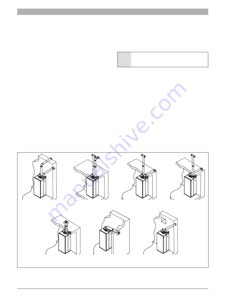
The following figure shows the acceptable piping installation for venting 

and combustion air.

Fig. 25   

Two pipes side wall 

(Direct venting)

Two pipes vertical 

(Direct venting)

Air intake side wall, 

vent vertical 

(Direct venting)

Air intake vertical, 

vent side wall

(Direct venting)

Concentring 

vertical pipe

(Direct venting)

Concentring side 

wall pipe

(Direct venting)

One pipe venting 

side wall (or vertical)

(Not direct venting)

Содержание Buderus SSB255

Страница 1: ...of the technical documents that must be handed over to the owner or operator of the heating system Explain to the owner or operator how to use the heating system using the operating instructions Make sure that they are familiar with all required information for the safe and proper operation of the heating system NOTICE In Massachusetts this appliance must be installed by a licensed plumber or gas ...

Страница 2: ...air piping system 24 4 7 2 Connecting flue gas systems 25 4 7 3 Installation of the exhaust and air intake system 25 4 7 4 Vent and combustion air pipe length For single boiler installations 28 4 7 5 Approved examples of horizontal and vertical venting installation 29 4 7 6 Multiple boiler 32 4 7 7 De rating for altitude installation 33 5 Commissioning for single boiler application 34 5 1 Switchin...

Страница 3: ...s or formation Make sure that inlets and outlets are not reduced in size or closed If faults are not corrected immediately the boiler must not be operated until all faults have been corrected Inform the system operator and or owner of the fault and the danger in writing When working on the flue gas venting equipment or vent damper leakage of flue gases may endanger the lives of people Carefully ob...

Страница 4: ...ty equipment Do not pull or twist the electrical wires from the boiler even if the device is disconnected from the main power supply Do not obstruct or reduce the ventilation openings Do not install the unit outdoors Do not leave any combustibles or containers of flammable substances in the room where the boiler is installed Keep packing material out of reach of children as it can be potentially d...

Страница 5: ... s warranty In some heating applications like pool spa or process water heating a heat exchanger must to be installed 2 4 Environmental responsibility disposal Environmental responsibility is one of the fundamental company policies of the Bosch Group We regard quality of performance economy and environmental responsibility as equal objectives Environmental protection laws and regulations are stric...

Страница 6: ... Gas inlet 1 NPT D Flue exhaust 3 80mm E Intake air 3 80mm 60 3 16 1529mm 19 19 32 498mm 17 21 32 448mm 61 9 16 1564mm 21 21 32 550mm G B D E A C F 23 31 32 609mm 56 7 16 1434mm 47 1 32 1195mm 48 7 16 1231mm 49 27 32 1266mm 5 7 16 138mm 58 7 8 1496mm 13 11 16 348mm 21 5 8 549mm 2 3 32 53mm 10 1 16 256mm 5 1 2 140mm 18 457mm 16 19 32 422mm 15 7 32 386mm 16 17 32 420mm ...

Страница 7: ... D Flue exhaust 4 110mm E Intake air 4 110mm 60 3 16 1529mm 19 19 32 498mm 17 21 32 448mm 21 21 32 550mm G B D E A C F 23 31 32 609mm 56 7 16 1434mm 47 1 32 1195mm 48 7 16 1231mm 49 27 32 1266mm 5 7 16 138mm 58 7 8 1496mm 13 11 16 348mm 21 5 8 549mm 2 3 32 53mm 18 457mm 16 19 32 422mm 15 7 32 386mm 16 17 32 420mm 61 9 16 1564mm 10 1 16 256mm 5 1 2 140mm ...

Страница 8: ...lue exhaust 4 110mm E Intake air 4 110mm 60 3 16 1529mm 19 19 32 498mm 17 21 32 448mm 21 21 32 550mm G B D E A C F 23 31 32 609mm 56 7 16 1434mm 47 1 32 1195mm 48 7 16 1231mm 49 27 32 1266mm 5 7 16 138mm 58 7 8 1496mm 13 11 16 348mm 21 5 8 549mm 2 3 32 53mm 18 457mm 16 19 32 422mm 15 7 32 386mm 16 17 32 420mm 61 9 16 1564mm 10 1 16 256mm 5 1 2 140mm ...

Страница 9: ... 512 Only 13 Min pressure switch For SSB 512 only Location should be burner side of gas valve 14 Automatic air vent 15 Low water cut off probe 16 High limit temp safety switch 17 Spark electrode 18 Heat exchanger 19 Condensate manifold 20 Air pressure switch connection 21 Low point drain valve 22 Heat exchanger return pipe 23 Return temperature probe 24 Wiring Control Panel 25 Main shut off gas va...

Страница 10: ...X type IIA IIB CPVC PVC PP PP Flex Stainless Steel AL29 4C IPEX type IIA IIB CPVC PVC PP PP Flex Stainless Steel AL29 4C IPEX type IIA IIB Max operating temperature F C 194 90 194 90 194 90 Max HE allowable temperature F C 210 98 9 210 98 9 210 98 9 Ambient storage temperature dry F C 5 to 150 15 to 65 5 to 150 15 to 65 5 to 150 15 to 65 Ambient functioning temperature F C 32 to 120 0 to 49 32 to ...

Страница 11: ...a residential boiler Fig 7 Thermal Efficiency Curves SSB399 Thermal Efficiency Return Water Temperature F 36 Degree Rise 86 88 90 92 94 96 98 100 70 80 90 100 110 120 130 140 150 160 170 100 input 30 input 20 input Thermal Efficiency Return Water Temperature F 36 Degree Rise 86 88 90 92 94 96 98 100 70 80 90 100 110 120 130 140 150 160 170 100 input 30 input 20 input ...

Страница 12: ...S SSB 12 Product description Fig 8 Thermal Efficiency Curves SSB512 Thermal Efficiency Return Water Temperature F 36 Degree Rise 86 88 90 92 94 96 98 100 70 80 90 100 110 120 130 140 150 160 170 100 input 30 input 20 input ...

Страница 13: ...allation of hard wired carbon monoxide detectors In the event that the side wall horizontally vented gas fueled equipment is installed in a crawl space or an attic the hard wired carbon monoxide detector with alarm and battery back up may be installed on the next adjacent floor level In the event that the requirements of this subdivision can not be met at the time of completion of installation the...

Страница 14: ... temperatures at or near freezing or temperature that exceed 120 F 49 C while in operation Failure to properly locate this unit can result in premature failure This appliance must be installed in a location so that any water leaking from the unit or piping connections or relief valve openings will not cause damage to the area surrounding the unit or any lower floors in the structure When such loca...

Страница 15: ... below 7 grains Filling with chlorinated water is acceptable if chlorine levels are below 100 ppm Consult a local water treatment specialist for recommendations if any of the above is outside the stated ranges When using oxygen permeable PEX the system must be separated from the boiler by a heat exchanger A correctly sized and working expansion vessel must be installed Do not exceed the maximum pe...

Страница 16: ...ed with a pressure relief valve PRV The relief pressure for each valve for each model of the boiler is shown in the following table Boiler model Relief Pressure SSB255 30 psi 2 07 bar SSB399 30 psi 2 07 bar SSB512 75 psi 5 17 bar A 75psi pressure relief valve can be purchased separately and field installed The pressure relief valve PRV must be piped to a suitable drain to prevent injury if the val...

Страница 17: ...h the boiler circuit depending on the flow rate SSB255 0 1 2 3 4 5 6 7 8 0 5 10 15 20 p Feet of Head Flow rate GPM Fig 12 SSB255 Pressure drop m m It is important to ensure the pump has the correct flow rate for the system to avoid a low water circulation situation In event of an inadequate flow rate the safety devices of the boiler will automatically stop the burner ...

Страница 18: ...tallation SSB399 0 2 4 6 8 10 12 14 16 18 0 5 10 15 20 25 30 35 p Feet of Head Flow rate GPM Fig 13 SSB399 Pressure drop SSB512 0 5 10 15 20 25 30 35 40 0 5 10 15 20 25 30 35 40 p Feet of Head Flow rate GPM Fig 14 SSB512 Pressure drop ...

Страница 19: ...meter of the condensate drain pipe down stream Never use copper pipes or of other material not intended for the specific purpose because the action of condensate will cause a rapid deterioration Check that the condensate drain pipe is adequately sloping towards the discharge point avoiding high points which can inhibit the flow of condensate Install the condensate pipe in such a way so as to avoid...

Страница 20: ...shown in Fig 19 4 5 4 Outside temperature sensor If outside temperature control is to be used the outside probe needs to be connected to terminals 7 and 8 as shown in Fig 19 The outside probe shall be installed on an outer wall North or North East away from windows door and ventilation grids Never install the probe in a position exposed to the sun The maximum length is 300 100 meter if the cable l...

Страница 21: ...blu brn bl blu g brn 3 4 bl bl blu brn o blu GND Ther mostat Manual Reset Switch Normally Closed Opens to Reset Alternate Chassis Ground Connection External Test Switch Normally Closed Opens to Test RESET GND AC COMMON TEST 24 VAC HOT PROBE P CHASSIS GROUND Via Boiler Piping AR1 AR1 120V 24V 210 210 210 208 208 208 209 209 209 214 214 214 HIGH VOLTAGE LOW VOLTAGE IN OUT HIGH Tank Sensor OUT DOOR M...

Страница 22: ...ausing property damage personal injury or loss of life Before carrying out electrical work Disconnect the appliance from the power supply at the emergency shutoff switch or by disengaging the heating system circuit breaker Take appropriate measures to prevent accidental reconnection The installer is resp onsible for the proper conversion of this appliance The conversion is not complete until the o...

Страница 23: ...rs Chlorine based swimming pool chemicals Calcium chloride Sodium chloride used for water softening Refrigerant leaks Paint or varnish removers Hydrochloric acid muriatic acid Cements and glues Antistatic fabric softeners used in clothes dryers Chlorine type bleaches detergents and cleaning solvents found in household laundry rooms Adhesives used to fasten building products and other similar produ...

Страница 24: ... vent and the combustion air inlet lines must be supported to prevent sagging per the vent manufacturer s instructions Do not mix components from different systems The vent system could fail causing leakage of flue products into the living space Use only approved materials Use of cellular core PVC and CPVC for venting system is not allowed a a WARNING Improper venting due to failure to comply with...

Страница 25: ...iameters 3 80mm 4 100mm 4 100mm Tab 3 Insert the exhaust pipe and the air intake pipe as shown in the following figure Fig 26 Insert the flue exhaust pipe A completely into the adapter and tighten the clamp B present in the flue exhaust adapter Insert the air intake pipe C completely into the adapter and tighten the clamp D present in the air intake adapter The correct flow direction into two pipe...

Страница 26: ...y USA 6 feet 915 mm above forced air inlet Canada It is not recommended to terminate vent above any door or window condensate can freeze causing ice formations Do not use chimney as a raceway if another boiler or fireplace is vented into or through chimney All PVC CPVC vent pipes must be glued except for the flue gas adapter pipe connection DO NOT use PVC when using anti freeze in the primary circ...

Страница 27: ... and glues of the certified vent system must be from a single system manufacturer and not intermixed with other system manufacturer s vent system parts For installations in Canada field supplied plastic vent piping must comply with CAN CSA B149 1 latest edition and be certified to the Standard for Type BH Gas Venting systems ULC S636 The supplied vent connector and separate available vent terminat...

Страница 28: ...ws 7 ft 12 ft 14 ft 14 ft 19 ft Tee 12 ft 19 ft 21ft 22 ft 29 ft Tab 9 Equivalent length for PP pipes For the equivalent vent length of Stainless Steel AL29 4C venting material and the roof and wall terminals please refer to the installation manual of the vent system supplier To calculate the allowed length of a vent and combustion air system follow this example When using a SSB255 with 3 80 mm PP...

Страница 29: ...features which can be subject to degradation from exhaust gases If multiple boilers are installed in a row allow at least 1 foot 305 mm clearance between the vent termination of one and the combustion air intake of the other In the following figures Fig 29 to Fig 41 the combustion air intake pipe is indicated with the number 1 one and the exhaust vent pipe with the number 2 two Fig 29 Horizontal v...

Страница 30: ... 33 Vertical venting system sealed combustion Y 12 above maximum snow level or at least 24 whichever is greater Fig 34 Vertical venting system sealed combustion X 12 Y 12 above maximum snow level or at least 24 whichever is greater Fig 35 Horizontal venting system sealed combustion X Y 2 1 1 2 Y 1 2 Y X Y X X 1 2 1 2 2 ...

Страница 31: ...on 3 is a wall termination Fig 37 Horizontal venting system sealed combustion X 4 102 mm Fig 38 Horizontal concentric system sealed combustion Fig 39 Vertical venting system sealed combustion X 12 305 mm Y 12 above maximum snow level or at least 24 whichever is great 2 3 1 1 2 X 1 2 Y X 1 2 ...

Страница 32: ... air inlet must terminate at the same height Fig 42 Concentric vent and combustion air vertical termination X 12 Y 12 18 for Canada and or per CAN CSA B149 1 above highest snow level Maximum 24 above roof Fig 43 Concentric vent and combustion air horizontal termination X 1 min or 2 max Y 24 Note the level of the termination must be the same at 12 min from grade or snow line Fig 44 Multiple air and...

Страница 33: ...7122 4000 373381 367235 361090 354944 5000 360571 354637 348702 342767 6000 347761 342037 336314 330590 7000 334952 329439 323926 318413 8000 322142 316840 311538 306235 9000 309333 304241 299150 294059 10000 296522 291642 286762 281881 Tab 12 De rating table for SSB399 input BTU hr range of the length of the vent and combustion air pipe installed referred to the maximum equivalent length Altitude...

Страница 34: ...anguage Unit type Date Time Other settings Date Time Date Sun 10 25 2015 Time 03 02 pm Time Zone Settings Display Settings 5 Commissioning for single boiler application Fig 48 No Description 1 ON OFF power switch 2 Reset button 3 Menu button 4 ESC button 5 PC service connection 6 OK button 7 UP DOWN LEFT RIGHT button 8 Display 5 1 Switching the appliance ON OFF Switch the appliance ON using the ON...

Страница 35: ...outdoor reset The DWH setpoint can only be changed when the DHW function is enabled See section 5 5 Parameters list It is possible to change the CH and the DHW setpoint directly from the first display page logically the change of the two setpoint must to be enabled when the text in the lower left side is CH Setpoint press the RIGHT button The value shown in the lower right side will be highlighted...

Страница 36: ...e password N 0000 USER Level 2 password 0300 INSTALLER 5 6 Outdoor reset To set the outdoor reset curve enter in Central Heating CH menu and press OK The display will appear as follow Fig 66 Des Supply T and Des Outd T will be highlighted to change either value press OK Use up down arrows to change the Des Supply T Use the left right arrows to change the Des Outd T 2 Press ok to save changes 3 Use...

Страница 37: ... F 1 8 F 25 Warm Weather Shutdn C F 69 8 F 35 6 F 95 F 1 8 F 26 Boost Temp Increment C F 0 F 0 F 54 F 0 9 F 27 Boost Time Delay Minutes 20 1 120 1 28 Night Setback Temp C F 18 F 0 F 90 F 0 9 F 29 Weather Setpoint C F 68 F 32 F 122 F 0 9 F 35 DHW Mode 0 0 2 1 36 DHW Tank Hyst Down C F 7 2 F 0 F 36 F 0 9 F 37 DHW Tank Hyt Up C F 0 F 0 F 36 F 1 8 F 38 DHW Tank Supply Extra C F 54 F 0 F 54 F 0 9 F 42 ...

Страница 38: ...iption Unit Default Min Max Step 93 Fan Speed Minimum RPM 60 94 Fan Speed Ignition RPM 60 97 Appliance Model 1 6 1 98 Gas Type NG NG LPG 99 Flue length range 1 1 4 1 Tab 15 Level 2 parameters Depend on appliance type The value for this parameter is 1 for SSB512 2 for SSB399 3 for SSB225 ...

Страница 39: ...he fan speed Wait 2 or 3 minutes to to reach steady state conditions and record the CO2 value To adjust the CO2 value at the maximum power turn the screw A shown in Fig 69 for SSB255 and in Fig 70 for SSB399 and SSB512 allen type wrench is necessary for this adjustment Fig 68 Gas valve screw regulation for SSB255 Fig 69 Gas valve screw regulation for SSB255 Fig 70 Gas valve screw regulation for SS...

Страница 40: ...ABLED To enable frost protection simply adjust parameter 89 to ENABLE When the frost protection is enabled Parameter 90 Frost Protection Setpoint has to be set Parameter 90 has a default setting of 50 F and can be adjusted from 33 68 F When the supply temperature falls below the value set by the parameter 90 the boiler pump starts If the supply temperature continues to fall and reaches 9 F 5 C bel...

Страница 41: ...rol had a blocking error for more than 20 hours in a row Press RESET button to display the Blocking error description Remove the cause of the Blocking error Fan Error 12 Fan MF deviation for more than 60 sec a Check for 120 Vac power connection of the fan b Check PWM connection of the fan a If no 120 VAC voltage is present replace the power control board b If no PWM signal is present replace power...

Страница 42: ...ame Error 2 54 Flame is detected in a state in which no flame is allowed to be seen Replace the power control board Water Level Detect 55 Low water level detected Water Level Meas 56 Low water level measurement error Low Water Cutoff Error 57 Low water sensor error Check the LWCO If the LWCO is in alarm try to reset it Low Water Pressure Error 58 Low water pressure error Low Water Pressure Sensor ...

Страница 43: ...onnections b Check the supply temperature sensor a If the wiring is damaged replace it b Verify that the temperature sensor has the correct resistance values If values are incorrect sensor must be replaced T Return Shorted 81 Return sensor shorted a Check the integrity of the wire connections b Check the return temperature sensor a If the wiring is damaged replace it b Verify that the temperature ...

Страница 44: ...e gas replace gas valve as needed Hard ignition poor ignition Check gas type Check inlet gas pressure adjust as needed Check power supply Check electrodes for visual damage replace as needed Check flue gas system clean or repair as needed Check gas air ratio replace gas valve as needed Check gas valve replace as needed Check burner replace if required Tab 20 6 3 Sensor Resistance table Temperature...

Страница 45: ...k modulation range check gas valve closing after burner stop Annually Check control parameters Annually Check for gas piping leak Annually Check wiring and connection Annually or every 2000 hours Which occurs first Tab 23 Licensed contractor gas fitter maintenance inspection schedule Time interval Maintenance Annually Verify startup Annually Verify the flame Annually Check relief valve Annually In...

Страница 46: ... boiler control and module installation manuals for additional detailed information 8 1 Multiple zone with indirect tank pump for each zone Fig 73 The following system diagrams are showing primary secondary piping As alternative a appropriate sized low loss header can also be used When using primary secondary piping please follow the following guidelines Fig 74 T T T T Zone relay X X T T DHW Senso...

Страница 47: ... Heating Mode 0 Outdoor air sensor not present 1 Outdoor air sensor present Reset curve activated 2 Mod Pump Mode 2 Enabled CH pump and DHW pump 35 DHW mode 0 No indirect sanitary water installed 1 Indirect sanitary water with sensor 2 Indirect sanitary water with tank thermostat If CH mode is set to 1 and an outdoor air sensor is present set the reset curve parameter as follows to set these value...

Страница 48: ...e Fig 76 Pressure By pass Expansion Tank Auto Fill Air Eliminator Isolation valve Condensate drain Outdoor air sensor Room Thermostat Flow Check Supply sensor Heating zone Domestic Hot Water Zone Valve Purge Drain Relief valve and pressure gauge Back flow preventer Zone relay X X optional 1 2 3 4 5 ...

Страница 49: ...l Heating Mode 0 Outdoor air sensor not present 1 Outdoor air sensor present Reset curve activate 2 Mod Pump Mode 2 Enabled CH pump and DHW pump 35 DHW mode 0 No indirect sanitary water installed 1 Indirect sanitary water with sensor 2 Indirect sanitary water with tank thermostat If CH mode is set to 1 and an outdoor air sensor is present set the reset curve parameter as follows to set these value...

Страница 50: ...ON Change the position of the S4 switch only when the boiler is off Each cascade boiler has to be identified by an address parameter N 73 Boiler Address different from the others To define these address follow the steps below Switch on the Primary boiler and set the parameter N 73 Boiler Address to 1 Switch off the Primary boiler Switch on the second boiler and set the parameter N 73 to 2 Switch o...

Страница 51: ... Fill Air Eliminator Shut off valve Condensate drain Outdoor air sensor Room Thermostat Supply sensor Circulator Purge Drain Relief valve and pressure gauge Back flow preventer Indirect Tank Heating zone Heating Return Indirect return Primary Bolier Secondary Bolier optional Indirect tank sensor tank not shown 8 2 9 1 7 6 3 4 5 ...

Страница 52: ... 5 8 6 1 2 3 4 5 6 7 8 9 10 11 12 13 14 CASCADE LINK MOD BUS Gas Switch Out Door DHW Tank Sensor Room Thermostat Supply Sensor N L 120 V Neutral Ground 120 V Line 120 V Neutral Ground 120 V Line Boiler pump 9 Supply sensor CH pump N L 1 7 Primary boiler Secondary boiler 4 Cascade link 4 Cascade link GND GND GND GND GND GND GND GND GND GND 101 102 103 104 105 106 107 108 109 116 118 117 L N L N L N...

Страница 53: ...Device 101 102 103 Boiler pump 104 105 106 CH pump 107 108 109 DHW tank pump The high voltage connections for Secondary boiler are Terminal Number Device 101 102 103 Boiler pump 8 3 1 Settings Set the parameters as indicated in the following table for the parameter list see section 5 5 Parameters list No Description Value Comment 1 Central Heating Mode 0 Outdoor air sensor not present 1 Outdoor ai...

Страница 54: ...put Notes regarding under or over pressure operation Get setting and flue gas test Gas conversion NG LPG propane Gas pressure W C mbar Gas static supply pressure W C mbar Selected maximum output MBH KW Selected minimum output MBH KW Flow rate at maximum nominal output gpm l min Flow rate at minimum nominal output gpm l min Net calorific value HiB per gas supplier MBTU ft3 kwh m3 CO2 at maximum nom...

Страница 55: ...cal connections checked notes Condensate trap filled Carry out a combustion air flue gas test Function check carried out Tightness test carried out on the gas and water sides Commissioning includes checking the setting a visual heating leak test and a functional check oh the boiler and control The system installer conducts a test of the heating system This system has been checked to the extent des...

Страница 56: ...6720818454 2016 02 US SSB 56 Spare parts 10 Spare parts Fig 82 1 2 4 8 9 3 5 6 7 17 24 18 19 17 20 12 13 10 14 15 16 21 23 19 23 22 22 11 25 ...

Страница 57: ... 738 004 910 12 Right frame 7 738 004 911 12 Right frame 7 738 004 912 12 Right frame 7 738 004 913 13 Left frame 7 738 004 914 13 Left frame 7 738 004 915 13 Left frame 7 738 004 916 14 Mounting bracket pressure differential switch 7 738 004 917 15 Mounting bracket return pipe 7 738 004 918 16 Mounting bracket condensate collector 7 738 004 919 17 Handle Front Panel 7 738 004 920 18 Lock and leve...

Страница 58: ...20818454 2016 02 US SSB 58 Spare parts 7 6 5 4 8 9 3 2 36 37 13 11 12 10 35 33 21 12 16 26 37 15 38 27 26 21 24 19 41 42 30 32 44 34 31 43 29 28 23 25 24 7 6 5 20 21 21 1 45 Fig 83 Shown on Fig 85 Fig 86 ...

Страница 59: ...24 O ring hx return adapter tube side 1 36x0 14in 34 5x3 5mm NBR 7 738 004 952 25 Boiler Return pipe 7 738 004 953 25 Boiler Return pipe 7 738 004 954 25 Boiler Return pipe 7 738 004 955 26 Frame support system supply return adapters 7 738 004 956 27 System return adapter 2 50mm 7 738 004 957 27 System return adapter 1 1 2 38mm 7 738 004 958 28 Male adapter Ø 0 27 inch hose barb x thread 7 738 004...

Страница 60: ...6720818454 2016 02 US SSB 60 Spare parts 6 75 6 5 4 6 5 3 2 1 7 8 9 10 16 15 18 17 14 13 12 11 21 20 23 24 25 19 Fig 84 ...

Страница 61: ... 005 046 11 Transformer 24V 0 6 amps 7 738 005 047 12 LWCO circuit board 7 738 005 048 13 Fuse carrier 7 738 005 049 14 Red LED light 7 738 005 050 15 Fuse 6 A 7 738 005 051 16 Fuse 0 125 A 7 738 005 052 17 Test push button 7 738 005 053 18 Manual Reset push button 7 738 005 054 19 Wiring harness SSB 7 738 005 055 19 Wiring harness SSB 7 738 005 108 19 Wiring harness SSB 7 738 005 056 20 Outdoor S...

Страница 62: ...6720818454 2016 02 US SSB 62 Spare parts 8 9 6 3 31 25 26 27 13 30 15 16 17 14 23 22 18 11 12 10 19 4 5 7 24 32 33 2 1 34 35 Fig 85 SSB255 ONLY ...

Страница 63: ...r 7 738 005 011 13 Venturi SSB 255 7 738 005 013 14 Washer gas pipe 1 25 mm 7 738 005 014 15 Adapter air intake tube SSB 255 7 738 005 017 16 Clamp for flex pipe air intake 7 738 005 019 17 Flexible pipe air intake SSB 255 7 738 005 021 18 Washer gas pipe 3 4 19 05mm 7 738 005 023 19 Gas pipe SSB 255 7 738 005 025 22 Frame support gas pipe 7 738 005 029 23 Gas connection 1 7 738 005 030 24 Sight g...

Страница 64: ...6720818454 2016 02 US SSB 64 Spare parts 1 2 3 4 5 6 7 8 9 26 25 27 24 11 10 12 13 15 14 14 16 16 17 17 14 18 19 22 14 39 39 41 42 23 21 20 40 43 44 Fig 86 SSB399 SSB512 ...

Страница 65: ...5 016 16 Gas valve adapter 7 738 005 018 17 Gas valve washer SSB 399 512 7 738 005 020 18 Gas valve SSB 399 512 and washers 7 738 005 022 19 Gas Pressure Switch low SSB 512 7 738 005 024 20 Gas Pressure Switch high SSB 512 7 738 005 026 21 Gas pipe inlet side of gas valve 7 738 005 027 21 Gas pipe inlet side of gas valve 7 738 005 028 22 Frame support gas pipe 7 738 005 029 23 Gas connection syste...

Страница 66: ...6720818454 2016 02 US SSB 66 Spare parts Notes ...

Страница 67: ...SSB 6720818454 2016 02 US Spare parts 67 Notes ...

Страница 68: ...echnology Corp 50 Wentworth Avenue Londonderry NH 03053 Tel 603 552 1100 Fax 603 965 7581 www boschheatingandcooling com U S A Bosch Thermotechnology Corp reserves the right to make changes without notice due to continuing engineering and technological advances ...

Отзывы: