


ACS 653, ACS 663 Service Manual
SP00D00624
2021-04-08
Robert Bosch GmbH
26
Introduction
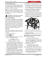
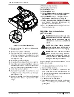
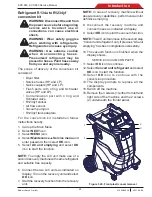
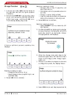
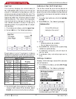
Figure 1-21. Ports assembly
3
5
7
9
4
6
8
19. Remove the HP (red) and LP (blue) flush
ports.
20. Remove the cap (3).
21. Place the contamination port (5) with its
o’ring and tighten at 15 Nm torque.
22. Place the Schrader valve in it (4) and tighten
at 0.35 Nm torque.
23.
Place the LP (blue) flush port (6) with its
o’ring and tighten at 15 Nm torque.
24. Place the Schrader valve in it (7) and tighten
at 0.35 Nm torque.
25.
Place the HP (red) flush port (9) with its
o’ring and tighten at 15 Nm torque.
26.
Place the Schrader valve in it (8) and tighten
at 0.35 Nm torque.
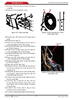
27. Open the service rear door.
28.
Remove the rear cover (above the service
door) by pushing it up and extract it by
pulling it out.
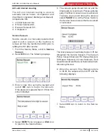
29.
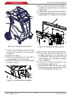
Install the air flow sensor (unit outside view,
see Figure 1-22) by securing it to the fan
assembly with two nuts.
30. Loosen 2 screws outside the frame to move
the fan assembly.
31. Connect the connector air flow sensor
to the air flow harness (unit inner view,
see Figure 1-22). Use tie-wraps to secure
the fan wires.
32. Connect the other end of the air flow
harness to the control board.
33.
Fix the fan assembly by tighten the 2 screws.
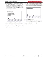
Figure 1-22. Air Flow Sensor (2 of 2)
-Unit inner view-
Figure 1-22. Air Flow Sensor (1 of 2)
-Unit outside view-
Nut
Nut
Connector
17. Remove the service hoses with quick
couplers.
18.
Remove the front plastic cover.


