

6 720 644 942
4
Appliance details
2.2
Unpacking the 520 HN heater
Before installing the unit, be certain you have the
correct heater for your type of Gas - Propane or
Natural Gas.
Identification labels are found on the
shipping box, and on the rating plate which is located on
the right side panel of the cover.
B
Installer must fill out checklist on back cover to
provide details in case service or warranty cov-
erage is required.
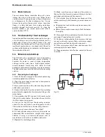
Fig. 2
Rating plate
A
Serial number
B
Type of gas
The box includes:
• Hot and cold water connection fittings
• Mounting screws
• Product registration card
• Installation manual
• Incandescent particle tray.
Do not lose this manual, there is a charge for a
replacement
.
Please complete and return the enclosed product
registration card.
The 520 HN is not approved or designed for:
• Manufactured (mobile) homes, RV's or boats
• Heating or other recirculating/pumping applications*
• Solar/preheat backup or high temperature booster
use
• Installation in bathroom, bedroom or other occupied
rooms normally kept closed.
* This includes domestic hot water circulator pump loop
systems that may be installed in home hot water system
prior to installing this unit. An approved recirculation
design can be found in chapter 3.9.
2.3
General rules to follow for safe
operation
1.
You must follow these instructions when you install
your heater. In the United States: The installation must
conform with local codes or, in the absence of local
codes, the National Fuel Gas Code ANSI Z223.1/
NFPA 54.
In Canada: The Installation must conform with CGA
B149.(1,2) INSTALLATION CODES and /or local
installation codes.
2.
Carefully plan where to install the heater. Proper
clearances must be followed.
3.
The appliance must be isolated from the gas supply
piping system by closing its individual manual gas
shutoff valve (not supplied with heater) during any
pressure testing in excess of ½ Psig (3.5 kPa).
The appliance and its gas connection must be leak
tested before placing the appliance in operation.
4.
Keep water heater area clear and free from
combustibles and flammable liquids. Do not locate the
heater over any material which might burn.
5. Correct gas pressure
is critical for the optimum
operation of this heater. Gas piping must be sized to
provide the required pressure at the maximum output of
the heater, while all the other gas appliances are in
operation. Check with your local gas supplier, and see
chapter 3.6 and 3.7 to verify proper gas line sizing.
6.
Should overheating occur or the gas supply fail to
shut off, turn off the gas supply at the manual gas shut
off valve, on the gas line. Note: manual gas shutoff valve
is not supplied with the heater.
7.
Do not use this appliance if any part has been
underwater. Immediately call a qualified service
technician to inspect the appliance and to replace any
part of the control system and any gas control which
has been underwater.
i
BOSCH is constantly improving its
products, therefore specifications are
subject to change without prior notice.