EN
16
Installation
www.bora.com
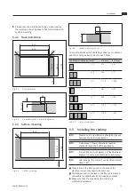
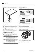
≥70
Ø50
±0,5
370
80-140
Fig. 5.9
Drill template
[1]
Cooktop
[2]
Worktop
[3]
Floor unit panel
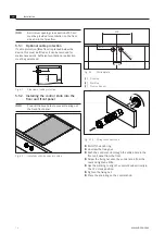
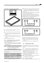
Fig. 5.10 Fitting the control knob
X
X
Pull off the knob ring.
X
X
Unscrew the fixing nut.
X
X
Push the control knob through the drilled hole in the
floor unit panel from the front.
X
X
Screw the fixing nut onto the control knob from the
rear and tighten a little.
X
X
Use the marking to align the control knob vertically in
the 12 o’clock position.
X
X
Tighten the fixing nut.
X
X
Place the knob ring on the control knob.
INFO
A minimum opening cross section of 50 cm²
must be provided for ventilation on the front
side and in the false floor.
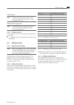
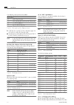
5.5.1 Optional cable protection
If cable protection (false floor) is planned below the
device, this must be fitted so it can be removed for
maintenance work. Sufficient ventilation or extraction
must be guaranteed.
>80
100
Fig. 5.7
Side view of cable protection
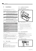
5.5.2 Installing the control knob into the
floor unit front panel
INFO
Pre-drill the bore holes to prevent tearing out
the fixed front panel.
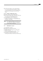
Fig. 5.8
Installed control knob and cooktop
Содержание PKT11
Страница 31: ......


