25
Installation and Maintenance Manual
Version : 10//28/2011
Issue
: THT-100-IMM-USA REV A6
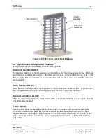
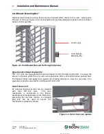
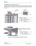
Top Rotor Assembly
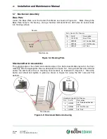
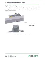
Place the upper flange blocks inside of the top of all three rotor arm posts and tighten down
using M10 bolts and spring lock washers.
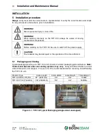
Note: if optional infill pieces are supplied. They
must be inserted before the top channel is installed. See figure 5.8 for illustration
.
Figure 5-8: Top Rotor Arm Assembly
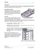
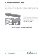
Optional Rotor Infill Pieces
(Powder Coat, Galvanized and Stainless models only)
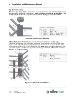
if equipped with optional rotor infill pieces, the bottom of the infill piece will include pins which
mount into the bottom flange first. Once the pins are inserted, move the top of the infill piece
into position and then insert the pins through the top.
Note
: ASTG, CSTG and EL models use
a snap in Infill pieces which do not require the mounting pins (Refer to ASTG/CSTG Installation
Appendix for further information.
Figure 5-9: Optional Rotor Infill Pieces
Hardware Used in this Process
Qty
Part #
Description
1
Varies
Upper Flange
6
HW038
M10 x 1.5 x 20 socket head
6
HW003
M10 Spring Lock Washer
Optional Hardware Used in this Process
Qty
Part #
Description
3
Varies
Infill Pieces
6
M6 x 40 socket head
1
2
3


