35
Installation and Maintenance Manual
Version : 10//28/2011
Issue
: THT-100-IMM-USA REV A6
WARNING!
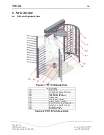
Persons should remain clear of the THT-100 top channel mechanism’s
moving parts.
5.11 General
The THT-100 will be pre-configured by Boon Edam and is ready for general use after
proper installation. Setting up the THT-100 for operation can be accomplished by using
the start procedure as described below.
•
Rotate the unit to its proper resting position.
•
Turn power to the main control box on. The solenoids should engage and you will hear the
lock(s) pull in.
•
Green LED on MCB indicates unit is ready for operation.
•
At this point, the unit is ready for operation.
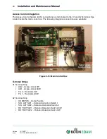
5.12 Time Out Relay Adjustment
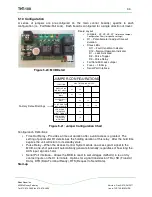
THT-100 units are equipped with a time out relay preset at the factory for approximately
10 second time out delay after a valid card read (see figure 5.16).
To adjust this setting carefully turn the potentiometer clockwise to minimize this time
(approx seven seconds), or counter-clockwise to increase this setting (max time approx
20 seconds).
5.13 Speed Control Adjustment (Optional)
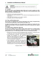
THT-100 units equipped with an optional speed control system are set during factory
assembly but may require additional field adjustment to achieve the desired dampening
during position cycle. The following procedure can assist in finalizing this setting.
•
Rotate the unit until you can feel the dampening system take effect (If dampening does
not take effect, the rotor arms will slam against the locking mechanism).
•
If more dampening is necessary, turn the speed control adjustment wheel clockwise to
increase the resistance of the dampening
mechanism until the desired force is applied.
Note: too much dampening can cause the unit to
brake too early which affects the throughput of the
unit and may damage the equipment.
•
If less dampening is necessary, turn the speed
control adjustment wheel counter-clockwise to
decrease the amount of dampening.
Note: too little
dampening can result in the unit slamming against
the locking system and may damage the equipment.
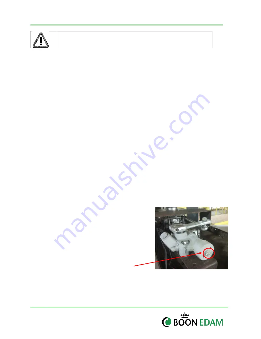
Adjustment Wheel
Figure 5-22: Speed Control

