5
7
8
6
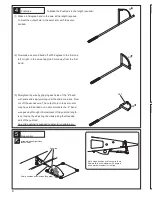
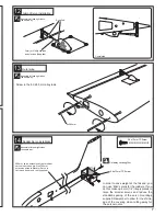
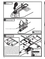
Main Landing Gear
Main Landing Gear
2
2
5.2mm Collar
3 x 4mm grub Screw
12
26
24
25
6
2 x 8mm TP Screw
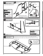
Noseleg
Noseleg Cover Plate
2.6 x12mm
TP Screw
16
2.6 x12mm TP Screw
2.6 x12mm
TP Screw
Requires some modification
on main gear cover.
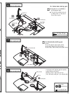
For Retractable landing gear
.
Not Supplied.
Not Supplied.
Not Supplied.
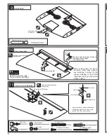
Main Landing Gear
Cut off shaded portion.
The main leg retracts should
be fitted about ½” inboard of
the centre wing tip.
2 x 8mm TP Screw
Trim the cover plate as required.
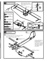
Fuselage/Wing joining
4mm
4mm Washer
4 x 50mm Bolt
NO:1007
2x8mm Screw
2
2
4 x 50mm Bolt
4mm Washer
2
NO:1007
2x8mm Screw
6
Cut away the covering from the slots on top of the centre wing. Place
the fuselage wing seat tabs into the slots. Mark the wingtop covering
along each side where the fuselage sits on the wing. Remove the
fuselage and carefully cut through the covering without damaging the
balsa abd strip off the the film between the marks you have made.
Now strip the covering carefully from the underside edge only of the
fuselage wing seat. Before finally gluing the wing to the fuselage, drill
and inset the alloy dowels to the front of the wing,. These will slip into
the parts No. 1007 supplied which should be epoxied to the former
using these dowels to adjust their position. Drill a 4mm hole through
the wing and plywood plate in the fuselage near the trailing edge and
fit the blind nuts on the topside of the ply. When satisfied with the fit,
epoxy the fuselage to the wing and tighten the bolts moderately with
washers to give a strong wing fix. The wing is not designed to be
removable.
Cut off shaded portion.
55mm
5.2mm Collar
3 x 4mm
grub Screw
For Retractable landing gear
Not Supplied.
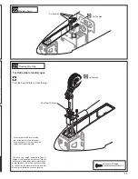
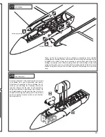
NOTE;
Do not fix plastic wheel wells until the
servo wires and air lines are in place.
Level off the surface around the retract units.
The height of the landing gear should be
approximately as follows;
Noseleg 11cms. and mains 12cms.
from underside surfaces to the wheel axles.
Not Supplied.


