background image

IDP1010 • Owner’s Manual

23

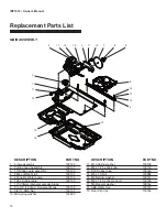
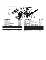
PRO.1 E.D.I. SYSTEM ASSEMBLY

1.  Switch box 

 130026

2.  Switch box cover 

 130027

3.  Power switch shield 

 100003 

4.  PC Board with plastic mount 

 130028

5.  Grounding plate 

 130044

6.  15A/125V Toggle switch 

 S1000-03

7.  Cable sandwich plate 

 130029

8.  Plastic leveling spacer 

 130030

9.  2 x 14AWG, 1 x 18AWG Tri-cable 

   unibody w/gland 

 130031

10. Pro.1 E.D.I. System LED panel decal 

 130032

11. LED Panel gasket ring 

 130033

12. Housing gasket ring 

 130034

13. M5 x 0.8 x 10L Cross screw 

 420121

14. M3 x 1.06 x 10L Cross tapping screw 

 130035

15. M3 Narrow washer 

 130036

16. M4 x 1.59 x 10L Cross tapping screw 

 130037

17. M4 x 1.59 x 12L Cross tapping screw 

 130038

18. M2.5 x 0.91 x 10L Cross tapping screw   130039

19. Push button PC board 

 130040

20. LED Panel backing 

 130041

21. Pathway plug (large) 

 130042

22. 18A/125V Circuit breaker 

 141038

23. Pathway plug (small) 

 130043 

     DESCRIPTION 

        PART NO

     DESCRIPTION 

        PART NO

10
20
11

17

3

12

5

22 21

23

14

15

18

8

19

16
4

1

9

7

13

2

6

Содержание IDP1010

Страница 1: ...afety and operating instructions carefully before operating the saw for the first time Retain manual for future reference ATTENTION Owner s Manual Keep for your records Optional Saw Stand IDP1010 Wet Tile Saw ...

Страница 2: ......

Страница 3: ...ting the Cutting Depth 7 Cleaning the Water Tray 7 Transporting the Saw 8 Proper Blade Use 9 Care And Maintenance 10 General Rules 10 Cleaning 10 Prolonged Period of Nonuse 10 Extreme Temperature 11 Water Pump Maintenance 11 Belt Replacement 11 Realignment 12 Leveling Adjustment 14 Electrical Specifications 15 Recommendations 15 Electrical Wiring Diagram 15 Extension Cord Chart 15 Troubleshooting 1...

Страница 4: ...recognized Any changes including changes in the performance or behavior of the machine must be reported to the supervisor If necessary stop the ma chine at once and secure it M In the case of a malfunction stop the machine imme diately and secure it Fix the problem as soon as pos sible N To stop and start the machine follow the operating in structions and observe any indicator lights O Keep out of...

Страница 5: ...by the foam packag ing and place it on a flat level working area Be sure that you have the following items before you discard the container Saw Plastic water tray Rear drip tray 10 saw blade Universal wrench Water pump Rip guide Owner s manual Drain plug See also page 23 for additional optional accessories Set Up Proceed to the following section to complete the assembly of the saw 1 Slide water pum...

Страница 6: ...uide allows convenient mea surements and promotes precision cuts Table Retention Device The device secures the cutting table when transporting the saw ABS Water Tray ABS is a lightweight alternative to stainless steel and offers excellent durability Features Specifications Bartell Morrison IDP1010 TILE SAW Motor Max Blade Capacity Cutting Length Cutting Depth Weight Dimensions 2 HP 115 V 60 Hz 3000...

Страница 7: ...ith one hand and use the other hand to tighten the nut with the universal wrench Make certain the flanges are pressed flush against the blade and that the nut is firmly tightened but do not over tighten 5 Loosen blade guard adjustment knob lower the blade guard and retighten the knob WATER PUMP INSTALLATION 1 Remove the water pump from the box and check that it is not damaged 2 Slide the pump onto th...

Страница 8: ...e to the left of the vertical channel in the cutting table Tighten threaded knob once in place 3 Place one corner of the material being cut in the vertical slot of the ruler guide and rest the adjoining edge flat against the rip guide 4 Now you are ready to make your cut PERFORMING MITER CUTS To make miter cuts an optional miter block must be pur chased 1 Place the lip of the miter block on the rul...

Страница 9: ...that the water tray is empty and dry 2 Unplug the power cord and store it in the water tray 3 Secure the cutting table to the front of the saw using the table retention device 4 Tighten the cutting depth control knob 5 Optionally the rear drip tray may be removed and set in the water tray for better handling figure 6 ...

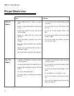
Страница 10: ... with blades larger than 10 Do not cut dry with blades marked Use Wet Do not exceed manufacturer s recommended maximum RPM Do not force blade into material Let blade cut at its own speed Dry Cut Blades In addition to the following always follow wet recommendations Use appropriate blade for material being cut Inspect segment blades for segment cracking or loss Do not use damaged blades Use proper s...

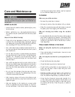
Страница 11: ...r rent circuit breaker If the fault current circuit breaker cuts the power supply the machine must be inspected by an authorized dealer prior to use CLEANING After every use of the machine Remove dirty water from container Remove dirt and mud from the bottom of the container Rinse the immersion pump with fresh water to prevent the water pump from clogging with residual dirt After wet cleaning and ...

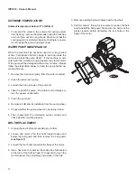
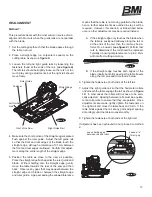
Страница 12: ...pump 3 Loosen the fixing screws of the pump lid 4 Take the lid off the pump Be careful not to damage or lose the gasket underneath 5 Clean the pump lid 6 Remove all dirt and incrustations from the pump wheel 7 Check whether the pump wheel can be easily turned 8 Then reassemble the immersion pump correctly and check whether it works properly BELT REPLACEMENT 1 Unplug the saw before proceeding any fu...

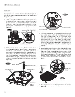
Страница 13: ... Rail Fastener Left Guide Rail Straight Edge Front of the Saw figure 8 means that the table is not moving parallel to the blade hence further adjustments as outlined in step 4 will be required However if scenario A or B described below occurs other adjustments may be required instead A If the straight edge only touches the blade when the table is positioned midway along the rail or at the ends of t...

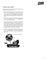
Страница 14: ...s procedure corrects another source of misalignment that occurs when the table s orientation is not parallel with the guide rails 1 Lift the saw up from within the water tray and place it on a flat level surface Use the universal wrench to loosen but not remove the fasteners from either end of both guide rails Move each rail away from the other so that the horizontal rollers are clear of the right ...

Страница 15: ...reely about one bolt see figure 15 Do this for both flat roller plates 3 Hold the table against the guide rails The flat rollers should reposition themselves to maintain contact with the guide rails If the table is not perpendicular to the blade lift the right side of the table instead to obtain the proper angle A square tool will be required to confirm the angle Tighten the socket bolts Check the tab...

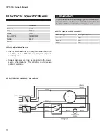
Страница 16: ...e to the power source while operating This will allow you to receive optimum electricity EXTENSION CORD CHART IDP1010 Power 2 HP Volts 115 V Amps 13 A Motor RPM 3000 RPM Cycle 60 Hz Phase 1 Wire Gauge Length of Cord No 12 25 No 10 50 No 8 75 Electrical Specifications To avoid permanent motor damage you must use the cor rect extension cord Never use more than one extension at a time Follow the chart...

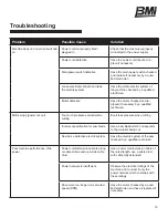
Страница 17: ...chnician Motor stops power cut out Too much pressure exerted while cutting Exert less pressure when cutting Incorrect specification for saw blade Use a saw blade which corresponds to the material being cut Saw has a defective electric system Have the electric system of the saw checked by a qualified technician Poor machine performance little power Power cord extension cable too long or cable still w...

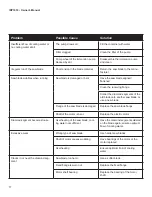
Страница 18: ... diamond segments of the old blade onto another saw blade or use a new blade Flange of the saw blade is damaged Replace the saw blade flange Shaft of the motor is bent Replace the electric motor Diamond segment becomes loose Overheating of the saw blade cool ing water not sufficient Have the diamond segment soldered on the blade again ensure optimum flow of cooling water Excessive wear Wrong type of ...

Страница 19: ... to wear The saw blade has slipped on the motor shaft when running The arbor of the saw blade must be fitted with an appropriate adaptor ring Check the receiving flange and have it replaced if necessary Saw blade shows blooming colors Saw blade overheating due to a lack of cooling water Ensure an optimum flow of cooling water Lateral friction when cutting The material feed is too high pro ceed more s...

Страница 20: ...neral purpose blade 8 Dia 5 8 15 9mm Universal flange 100136 9 5 8 11 UNC Nut 100137 10 M8 Spring washer 100080 11 M10 Spring washer 100138 12 M8 x 1 25 x 20L knob 100139 13 D30 Rubber plug 100140 14 M8 x 1 0 Nut 100086 15 M8 Narrow washer 100141 16 M8 x 1 25 x 16L Hex bolt 100109 17 M8 Regular washer 100142 18 ABS Water tray 100143 19 Rear drip tray 100144 DESCRIPTION PART NO DESCRIPTION PART NO 2...

Страница 21: ...081 18 M8 x 1 0 Nut 100082 19 M8 x 1 25 x 55L x 28 Cap socket hex bolt 100083 20 M6 x 1 0 x 20L Socket head hex bolt 100084 21 M8 x 1 25 x 70L x 28 Cap socket head hex bolt 100085 22 M8 x 1 25 Nylon nut 100086 23 M6 x 1 0 x 10L Hex bolt 100062 24 M8 x 1 25 x 12L Hex bolt 100087 25 Power switch shield 100088 26 Power switch boot 100089 27 15A Circuit breaker w reset button boot 100090 28 Power swit...

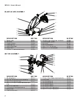
Страница 22: ...IPTION PART NO 5 2 4 7 6 8 12 11 9 1 Mounting block 100145 2 M2 2HP Entire brush motor assembly 100146 3 M8 x 1 25 x 25L Hex bolt 100147 4 M8 x 1 25 x 30L Countersunk socket hex bolt 100148 5 M8 x 1 25 Nylon nut 100082 6 Armature and winding assembly 100149 7 Motor cover 100150 8 Carbon brush cap 100151 9 17mm x 7mm Carbon brush set of 2 100152 10 Wind baffle 100153 11 M5 Spring washer 100154 12 M4...

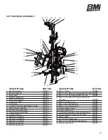
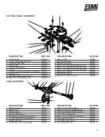
Страница 23: ...079 19 M8 x 1 25 x 20L Hex bolt 100109 DESCRIPTION PART NO DESCRIPTION PART NO CUTTING TABLE ASSEMBLY 1 7 18 15 9 16 12 3 11 13 10 14 6 17 5 19 8 4 2 LCBH ASSEMBLY 1 Bearing housing 100110 2 Blade shaft 100112 3 Rubber gasket 100113 4 Water channel cover 100114 5 M10 Male to D7 5 male connector 100116 6 7 Link 6 3 ID flat nose assembly 100117 7 Blade shaft pully 100118 8 Dia 16 5mm arbor inner flang...

Страница 24: ...decal 130032 11 LED Panel gasket ring 130033 12 Housing gasket ring 130034 13 M5 x 0 8 x 10L Cross screw 420121 14 M3 x 1 06 x 10L Cross tapping screw 130035 15 M3 Narrow washer 130036 16 M4 x 1 59 x 10L Cross tapping screw 130037 17 M4 x 1 59 x 12L Cross tapping screw 130038 18 M2 5 x 0 91 x 10L Cross tapping screw 130039 19 Push button PC board 130040 20 LED Panel backing 130041 21 Pathway plug ...

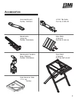
Страница 25: ... 41 Masterguide Template Base Optional Part No S1000 MG1 45 90 Rip Guide Part No S1000 35 Masterguide Optional Part No S1000 MG Saw Stand Optional Part No IDP1010ST Side Extension Table Optional Part No 100102 Miter Block Optional Part No S1000 34 ...

Страница 26: ... invoice along with serial numbers for all equipment should accompany all RMA requests All returned products must be in sellable condition include all components and be packed in original packaging The RMA number assigned by customer service must be clear ly marked on the accompanying packing slip Any returns not satisfying these conditions will be promptly returned to the customer at their expens...

Страница 27: ...nquiry or troubleshooting please don t hesitate to contact us We will do our best to answer your questions In some cases we may even refer you to a local sales representative that can better service you You can call us at the contact information listed below CUSTOMER SERVICE Phone 866 501 1683 Email blyons bartellmorrison com Web www bartellmorrison com ...

Страница 28: ...y service you must take the product or deliver the product freight prepaid in either its original packaging or packaging affording an equal degree of pro tection to any authorized Bartell Morrison service facility along with proof of purchase in the form of a bill of sale within the warranty period specified above Warranty may be void if additional damages are incurred during transpor tation due to...

Страница 29: ...12 INDUSTRIAL DRIVE KEYPORT NJ 07735 TEL 866 501 1683 www bartellmorrison com ...

Отзывы: