background image

29

NA

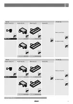
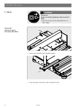
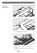
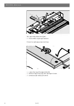
Routing the drawer bottom


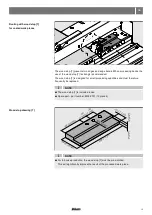
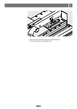
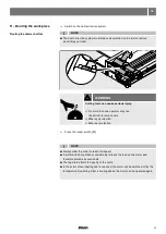
Switch on the dust extraction system.

NOTE


The dust extraction system must always be switched on in order to remove 

  wood chips and dust.

Cutting tools can cause serious injury.


 No more than one operator may use  
the bottom router at a time.


Wear eye protection.


Wear ear protection.

WARNING


Press the rocker switch [20].

NOTE


Always allow the motor to reach full speed.


A cutter with sharp blades considerably relieves the load on the motor and 

  therefore extends its service life.


The feed rate affects the quality of the notch.


In the event of overheating due to overload, the motor will be switched off by the 

  temperature monitoring. After a cooling phase the motor can be operated again.

H – Routing the work piece

20

Содержание M35.7200.NA

Страница 1: ...Safety set up operating and maintenance instructions Ensure that the instructions have been fully read and understood before operating the bottom router Only appropriately trained and authorized personnel may operate the bottom router ...

Страница 2: ...power supply Connecting the dust extraction system Routing with depth stop Routing with wood stop Panel thickness 15 to 16 mm 9 16 to 5 8 Panel thickness 17 18 19 mm 11 16 to 3 4 Stop bar Support stop Depth stop Wood stop Support Clamping the drawer bottom Routing the drawer bottom Clamping the back Routing the back Everyday cleaning Removing and installing the motor Cleaning the housing Removing ...

Страница 3: ...arts being described Intended use The bottom router is only intended to process drawer bottoms for the Blum LEGRABOX and TANDEMBOX The bottom router may only be used under the following conditions The bottom router may only be operated by fully trained personnel The bottom router is designed for professional traders Only particle board and medium density fibreboard MDF may be used as materials The...

Страница 4: ...ROOF with padlocks master switches or by removing starter keys WEAR PROPER APPAREL Do not wear clothing gloves neckties rings bracelets or other jewelry which may get cought in moving parts Nonslip footwear is recommended Wear protective hair covering to contain long hair Only attach the bottom router to a sufficiently stable table Operate with the bottom router only when the router carriage S1 is...

Страница 5: ...he bottom router to the power supply you must ensure that you have understood ALL the safety instructions warning signs and the instruction manual Warning signs The bottom router is only intended for use by one person Ensure that the average air velocity for dust extraction system is at least 20 m sec The negative pressure in the dust extraction system must be 250 300 mbar Failure to observe the i...

Страница 6: ...29 kg 1X230 V 50 60 Hz 1 05 kW Industriestrasse 1 Do not operate the machine without the dust extraction system attached and running Kick back Clamp bar must be engaged on the workpiece to prevent kick back Turn off dust extraction system and disconnect machine from electrical power before cleaning or servicing Machine must be properly secured before operation ...

Страница 7: ...iage Fixing board delivered loose Work top Clamping lever Support Depending on device type not part of the scope of delivery Part number M35 ZD19 Dust extraction socket Support stop Depth stop Wood stop Clamping plate Stop bar Transportation lock Cutter DM 44 11 3 6 12 13 14 8 7 9 10 2 4 5 S1 1 ...

Страница 8: ...3 24 14 20 M35 7200 NA Bottom router Reference diagram for Router carriage Sliding film Allen wrench SW3 Flange surface Notch cutter Spacer sleeve Cutter DM 44 Rocker switch TORX T20 TORX T15 TORX T9 21 20 24 22 23 14 ...

Страница 9: ... work piece Rocker switch The rocker switch 20 is used to switch the bottom router off and on Non stop operation is not possible In the event of overheating due to overload the motor will be switched off by the temperature monitoring After a cooling phase the motor can be operated again 8 20 ...

Страница 10: ...__________ 990 mm 39 Weight __________________________________________________________ 29 kg 64lb Only use in dry enclosed rooms Ensure there is sufficient lighting A table height of more than 900 mm 35 7 16 is recommended The specified width depth and height are minimum dimensions The bottom router must only be used on a stable work top WARNING The bottom router weighs 29 kg 64lb Failure to obser...

Страница 11: ...njury and material damage The following fixing methods are intended for the bottom router fixed attachment to the work top removable attachment to the worktop WARNING Screw the bottom router to the work top Removable attachment to worktop Measure the depth X of the workbench Requirement Table depth X at least 750 mm 29 9 16 X min Ø 5 mm min Ø 13 64 ...

Страница 12: ...he table length and screw to the frame Secure the bottom router to the work top with fixing boards 1 and screw clamps Removing the transportation lock Remove the transportation lock 11 The carriage of the bottom router is secured for transport X min Ø 5 mm min Ø 13 64 1 11 ...

Страница 13: ...ave the proper outlet installed by a qualified electrician lmproper connection of the equipment grounding conductor can result in a risk of electric shock The conductor with insulation having an outer surface that is green with or without yellow stripes is the The electrical connection must be performed by a qualified electrician The bottom router is designed for the voltage printed on the label o...

Страница 14: ...ediately This bottom router is intended for use on a circuit that has an outlet that looks like the one illustrated The bottom router has a grounding plug that looks like the plug illustrated Make sure the bottom is connected to an outlet having the same configuration as the plug No adapter is available or should be used with this bottom router lf the bottom router must be reconnected for use on a...

Страница 15: ...the wood stop 7 is strongly recommended The wood stop 7 is designed for small processing quantities and must therefore frequently be replaced The wood stop 7 is included loose Spare part part number M35 ZT01 10 pieces For in house production the wood stop 7 must be pre notched This will significantly improve the result of the processed work piece NOTE NOTE 7 ...

Страница 16: ... router Shorten the wood stop 7 by 32 mm Replacing the wood stop 7 The wood stop 7 becomes worn through frequent routing This can lead to torn edges on the work piece To avoid this the wood stop 7 must be reworked if necessary 7 7 ...

Страница 17: ...17 NA Reposition the wood stop 7 using the next through hole The wood stop 7 can be reworked twice 7 ...

Страница 18: ...tings Selecting Set up The cutter M35 ZF44 03 should not be used in the processing of panel thicknesses up to 16 mm 5 8 The spacer sleeve 24 must be mounted in place of the cutter For the product TANDEMBOX no further processing is necessary for panel thicknesses up to 16 mm 5 8 NOTE In scope of delivery 37 24 15 16 mm 9 16 5 8 16 5 8 38 1 1 2 8 5 16 ...

Страница 19: ...19 NA M35 0035 01 M35 ZT01 Support 5 Wood stop 7 Depth stop 6 Set up Processing Clamp work piece Route work piece 25 25 25 26 29 6 7 ...

Страница 20: ... Back 31 Drawer bottom 30 Drawer bottom 30 Cutter fittings Cutter fittings Stop bar 13 Stop bar 13 Selecting Selecting Set up Set up For restrictions for Blum products with panel thickness greater than 16 5 8 and up to 19 mm 3 4 see page 46 37 37 37 37 22 22 22 14 14 14 14 13 13 13 16 19 mm 5 8 3 4 19 5 13 16 16 5 8 19 5 13 16 16 5 8 19 5 13 16 16 5 8 16 5 8 38 1 1 2 19 5 13 16 8 5 16 ...

Страница 21: ...ort 5 Wood stop 7 Wood stop 7 Support stop 12 Support stop 12 Depth stop 6 Depth stop 6 Set up Set up Processing Processing M35 0035 01 M35 ZT01 M35 0035 01 M35 ZT01 Clamp work piece Clamp work piece Route work piece Route work piece 23 23 25 25 25 25 25 25 26 26 29 29 25 25 25 25 12 6 7 6 7 6 7 6 7 12 ...

Страница 22: ...mber M35 ZD19 F Set up WARNING Serious cuts Failure to heed this warning may result in personal injury The bottom router must be disconnected from the power supply Remove the stop bar 13 from the parked position Push the stop bar 13 into the runner of the bottom router 13 13 ...

Страница 23: ...upport stop 12 from the parked position Mount the support stop 12 in the working position Mount the depth stop 6 or wood stop 7 in the furthest forward position See page 25 Push the work piece to the support stop 12 stop bar 13 and depth stop 6 or wood stop 7 12 12 12 13 6 7 ...

Страница 24: ...er a right angle is present Loosen the screw of the support stop 12 Rotate the support stop 12 until a right angle is formed Screw the support stop 12 into place The support stop 12 must be aligned If there is no right angle proceed as follows 12 12 ...

Страница 25: ...rd position Positioning the depth stop 6 Positioning the wood stop 7 Mount the wood stop 7 in accordance with the drawer nominal length When processing the back 31 the wood stop 7 must always be mounted in the furthest forward position Support 5 Drawer bottom width 500 mm 19 11 16 swivel out the support 5 Swivel out the support 5 until the stop right angle 6 7 5 ...

Страница 26: ...ood chips on the work top 4 and stop surface as they can affect the accuracy of the notch or damage the surface of the work piece Lay the drawer bottom 30 on the bottom router as shown Push the drawer bottom 30 onto the stops as shown Clamping the drawer bottom 30 LEGRABOX TANDEMBOX 30 30 ...

Страница 27: ...e clamping lever 8 Check again that the work piece is lying flat against the stops Clamping the back 31 NOTE Lay the back 31 on the bottom router as shown There should be no wood chips on the work top 4 and stop surface as they can affect the accuracy of the notch or damage the surface of the work piece 30 8 6 7 K 31 ...

Страница 28: ...the stop bar 13 support stop 12 and stops 6 7 as shown CAUTION Keep your hands away from the clamp Keep the work piece 31 pressed against the stops Push down the clamping lever 8 Check again that the work piece is lying flat against the stops 8 6 7 31 12 13 31 ...

Страница 29: ...e Wear eye protection Wear ear protection WARNING Press the rocker switch 20 NOTE Always allow the motor to reach full speed A cutter with sharp blades considerably relieves the load on the motor and therefore extends its service life The feed rate affects the quality of the notch In the event of overheating due to overload the motor will be switched off by the temperature monitoring After a cooli...

Страница 30: ...rial Return the carriage S1 to its starting position when the motor is switched on Leave the rocker switch 20 in the starting position For the second notch repeat the work processes from Clamp work piece Switch off dust extraction system NOTE Never turn off the motor during the routing and return process This could damage the motor or the notch cutter 23 30 S1 S1 30 ...

Страница 31: ... with sharp blades considerably relieves the load on the motor and therefore extends its service life The feed rate affects the quality of the notch In the event of overheating due to overload the motor will be switched off by the temperature monitoring After a cooling phase the motor can be operated again Cutting tools can cause serious injury No more than one operator may use the bottom router a...

Страница 32: ...turn the carriage S1 to its starting position when the motor is switched on Leave the rocker switch 20 in the starting position For the second notch repeat the work processes from Clamp work piece Switch off dust extraction system NOTE Never turn off the motor during the routing and return process This could damage the motor or the notch cutter 23 S1 31 31 ...

Страница 33: ...s during cleaning All runners and bearings are maintenance free Dust and wood chips must not be removed using sharp edged or metallic objects Never use compressed air near the motor Wood chips may infiltrate the motor through the ventilation slots and therefore impair the motor s cooling system and service life Keep the motor ventilation slots free of dust and wood chips Clean the depth stop and l...

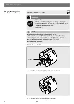
Страница 34: ...e cleaning and maintenance Removing the motor NOTE Gloves must always be worn when cleaning the cutter 23 Loosen the screw 41 with an SW 6 hex key 1 4 rotation 90 Carefully remove the motor 40 Damage to the cutting inserts is possible If the motor needs to be removed for maintenance cleaning or replacement purposes proceed as follows Swivel the shaft holder 2 by 90 degrees 40 41 2 ...

Страница 35: ...arefully on to the flange surface 21 Damage to the cutting inserts is possible Turn the motor 40 to the correct position Tighten screw 41 Installing the motor NOTE Pay attention to the motor position The motor s ventilation slot 40 must not be covered Risk of overheating Place the motor 40 in the shaft holder 2 21 40 41 S1 2 40 40 ...

Страница 36: ...nstalling the motor If the housing G of the carriage S1 is filled with wood chips or if the cutter is blocked proceed as follows Installing removing the cutter Turn the nut 42 clockwise using the IM spanner NOTE The thread on the motor shaft is a left hand thread Removing and installing the motor 34 34 G S1 42 24 ...

Страница 37: ...ofitting cutter DM 44 14 optional accessory Part number M35 ZD19 Removing and installing the motor Turn the nut 42 clockwise using the IM spanner Remove the spacer sleeve 24 Mount the cutter DM 44 14 34 42 24 14 ...

Страница 38: ...ng and maintenance Wear gloves Changing the pre cutter 50 Loosen the pre cutter screw 50 by turning it counter clockwise Clean the base of the pre cutter 50 using a dry cloth NOTE The blades should be changed in the following sequence Whenever the pre cutters 50 are turned for the second time the cutting inserts 51 should also be turned The pre cutter 50 has the highest load Sharp blades significa...

Страница 39: ...39 NA Clean the pre cutter 50 using a dry cloth Turn the pre cutter 50 90 degrees Tighten the screw in the pre cutter 50 by turning it clockwise NOTE Only the TORX key provided may be used 50 50 50 ...

Страница 40: ...5 7200 NA Bottom router Loosen the screw for the cutting insert 51 by turning it counter clockwise Clean the base of the cutting inserts 51 using a dry cloth Turn the cutting insert 51 180 degrees hex key SW3 51 51 ...

Страница 41: ...setting gauge 52 Tighten the screw for the cutting insert 51 by turning it clockwise NOTE After all four pre cutter positions have become worn the entire set consisting of pre cutters 50 and cutting inserts 51 must be replaced hex key SW3 0 51 52 51 ...

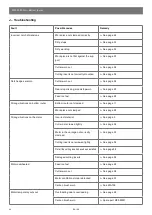
Страница 42: ...r not clamped See page 11 Work piece not clamped See page 26 Strong vibrations on the motor Incorrect material See page 3 Cutter not screwed tightly See page 36 Motor in the carriage not correctly clamped See page 35 Cutting inserts not screwed tightly See page 38 Not all the cutting inserts have been installed See page 38 Damaged cutting inserts See page 38 Motor overheated Feed too fast See page...

Страница 43: ...43 NA When ordering spare parts state the year of construction and serial number K Spare parts M35 ZF44 03 M35 ZF60 03 M35 ZW40 M35 ZW40W M35 ZW14W 10x 10x ...

Страница 44: ...tter Dust extraction socket Spanner 19 Allen key 6 Dispose of all mechanical components of the bottom router in accordance with local regulations Dispose of all electrical components of the bottom router in a separate collection for electrical and electronic appliances as per local regulations L Bottom router set ...

Страница 45: ... uncertainty ________________ 4 dB A Voltage _______________________________________________ 1x 230 240 V 50 60 Hz Power _______________________________________________________________ 1050 W Operation ____________________________________________ 5 40 C 41 F 104 F Storage _____________________________________________ 20 70 C 4 F 158 F Nominal length of drawer bottom ________________ 270 650 mm 10 ...

Страница 46: ... mm With the front stabilizer the drilling position and space requirement beneath need to be considered Bottom back drilling template ZML 7000 cannot be used Back with 16 5 8 to 19 mm 3 4 With SERVO DRIVE the drilling positions and space requirement have to be adjusted Back with 16 5 8 to 19 mm 3 4 With SERVO DRIVE the drilling positions and space requirement have to be adjusted The side stabilise...

Страница 47: ...47 NA Notes ...

Страница 48: ... 1 704 827 1345 Fax 1 704 827 0799 www blum com Blum Canada Limited 7135 Pacific Circle MISSISSAUGA ON L5T 2A8 CANADA Tel 1 905 670 7920 Tel 1 800 670 9254 Fax 1 905 670 7929 www blum com Blum partners worldwide can be found at BAU0054937336 IDX 00 IDNR 606 165 9 BA 166 1EA 06 15 Copyright Blum ...

Отзывы: