background image

508255-01

Page 17 of 19

Issue 2212

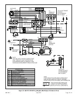
Figure 10. 4AC13/14/16 Wiring Diagram (Multi-Speed Condenser Fan)

Содержание BA13

Страница 1: ...sk of electrical shock Disconnect all remote power supplies before installing or servicing any portion of the system Failure to disconnect power supplies can result in property damage personal injury or death WARNING Sharp metal edges can cause injury When installing the unit use care to avoid sharp edges WARNING General Read this entire instruction manual as well as the instructions supplied in s...

Страница 2: ...isturb customer Leave some slack between structure and unit to absorb vibration Place a sound absorbing material such as Isomode under the unit if it will be installed in a location or position that will transmit sound or vibration to the living area or adjacent buildings In heavy snow areas do not locate the unit where drifting snow will occur The unit base should be elevated above the depth of a...

Страница 3: ...eping area or near windows Under eaves where water snow or ice can fall directly on the unit With clearance less than 2 ft from a second unit With clearance less than 4 ft on top of unit Rooftop Installations Install unit at a minimum of 6 above surface of the roof to avoid ice buildup around the unit Locate the unit above a load bearing wall or area of the roof that can adequately support the uni...

Страница 4: ...ng and foundation Any gap between foundation or wall and refrigerant lines should be filled with a vibration damping material If ANY refrigerant tubing is required to be buried by state or local codes provide a 6 inch vertical rise at service valve CAUTION Installation into an Existing R 22 System If the unit will be installed in an existing system that uses an indoor unit or line sets charged wit...

Страница 5: ...d that the existing line set and indoor coil be replaced NOTE LOW HIGH EXISTING INDOOR UNIT GAUGE MANIFOLD CYLINDER CONTAINING CLEAN R 410A TO BE USED FOR FLUSHING Positioned to deliver liquid refrigerant LIQUID LINE SERVICE VALVE INLET DISCHARGE TANK RETURN CLOSED OPENED RECOVERY CYLINDER RECOVERY MACHINE NEW OUTDOOR UNIT VAPOR LINE SERVICE VALVE VAPOR LIQUID 1 A B C D A Cylinder with clean R 410...

Страница 6: ...wn Sensing bulb insulation is required if mounted external to the coil casing sensing bulb installation for bulb positioning STUB END TEFLON RING LIQUID LINE ASSEMBLY WITH BRASS NUT DISTRIBUTOR ASSEMBLY 3 Install one of the provided Teflon rings around the stubbed end of the check expansion valve and lightly lubricate the connector threads and expose surface of the Teflon ring with refrigerant oil...

Страница 7: ...ssure side to liquid line service valve service port B Connect gauge set center port to bottle of nitrogen with regulator C Remove core from valve in vapor line service port to allow nitrogen to escape NITROGEN HIGH LOW USE REGULATOR TO FLOW NITROGEN AT 1 TO 2 PSIG B A C WHEN BRAZING LINE SET TO SERVICE VALVES POINT FLAME AWAY FROM SERVICE VALVE Flow regulated nitrogen at 1 to 2 psig through the l...

Страница 8: ...VES POINT FLAME AWAY FROM SERVICE VALVE PREPARATION FOR NEXT STEP 7 WRAP SERVICE VALVES To help protect service valve seals during brazing wrap water saturated cloths around service valve bodies and copper tube stubs Use additionalwater saturated cloths underneath the valve body to protect the base paint 4 FLOW NITROGEN Flow regulated nitrogen at 1 to 2 psig through the refrigeration gauge set int...

Страница 9: ...he valve on the high side of the manifold gauge set in order to pressurize the line set and the indoor unit E After a few minutes open one of the service valve ports and verify that the refrigerant added to the system earlier is measurable with a leak detector F After the line set has been connected to the indoor and outdoor units check the line set connections and indoor unit for leaks Use the fo...

Страница 10: ...uid refrigerant Open the manifold gauge valve 1 to 2 psig in order to release the vacuum in the line set and indoor unit G Perform the following Close manifold gauge valves Shut off HFC 410A cylinder Reinstall service valve cores by removing manifold hose from service valve Quickly install cores with core tool while maintaining a positive system pressure Replace stem caps and finger tighten them t...

Страница 11: ...ench with a hex head extension to back the stem out counterclockwise as far as it will go Use a 3 16 hex head extension for liquid line service valves and a 5 16 extension for suction line service valves 3 Replace the stem cap Tighten finger tight then tighten an additional 1 6 turn To Close Liquid or Suction Line Service Valve 1 Remove the stem cap with an adjustable wrench 2 Use a service wrench...

Страница 12: ...cess high voltage field wiring should be trimmed or secured away from the low voltage field wiring 2 High voltage power connections to 3 phase models is made to Pig Tail leads with field supplied splice connectors 3 Ground unit at unit disconnect switch or to an earth ground To facilitate conduit a hole is in the bottom of the control box Connect conduit to the control box using a proper conduit f...

Страница 13: ...lank space is provided on the unit rating plate to list the actual field charge Table 4 Refrigerant Charge Adjustment Liquid Line Set Diameter Oz Per 5 ft adjust from 15 ft line set 3 8 in 3 oz per 5 ft or 0 6 oz per 1 ft If line length is greater than 15 ft add this amount If line length is less than 15 ft remove this amount Mineral oils are not compatible with R 410A If oil must be added it must...

Страница 14: ...nser Coils Grass cuttings leaves dirt dust lint from clothes dryers and foliage from trees can be drawn into coils by movement of the air Clogged condenser coils will lower the efficiency of your unit and could cause damage to the condenser Periodically debris should be brushed from the condenser coils Use a soft bristle brush with light pressure only DO NOT damage or bend condenser coil fins Dama...

Страница 15: ...anty replacement parts are required the warranty must be processed through a qualified distribution location Homeowner Information ELECTRICAL SHOCK HAZARD Turn OFF electric power to unit before performing any maintenance or removing panels or doors FAILURE TO DO SO COULD RESULT IN BODILY INJURY OR DEATH WARNING Thermostat Operation The wall mounted thermostat controls your air conditioner The ther...

Страница 16: ...Page 16 of 19 508255 01 Issue 2212 Figure 9 4AC13 14 16 Wiring Diagram Single Speed Condenser Fan ...

Страница 17: ...508255 01 Page 17 of 19 Issue 2212 Figure 10 4AC13 14 16 Wiring Diagram Multi Speed Condenser Fan ...

Страница 18: ... L2 L1 208 230 60 1 GROUND TO 24 VAC POWER SOURCE 20 VA MINIMUM NEC CLASS 2 C Y1 A4 TIMED OFF CONTROL COMPRESSOR CONTACTOR COMPRESSOR CRANKCASE HEATER S40 K1 1 L2 208 230 60 1 BLACK YELLOW RED ORANGE RED BLACK H C F B4 C12 C S R B1 S40 RED HR1 2 3 1 S4 K1 A4 TO 24 VAC POWER SOURCE 20 VA MINIMUM NEC CLASS 2 S87 C Y1 YELLOW 2 YELLOW BLACK IF USING A4 CONNECT S4 TO TERMINAL 3 ON A4 CONNECT Y1 TO TERM...

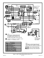
Страница 19: ...L1 208 230 60 1 GROUND TO 24 VAC POWER SOURCE 20 VA MINIMUM NEC CLASS 2 C Y1 A4 TIMED OFF CONTROL COMPRESSOR CONTACTOR COMPRESSOR CRANKCASE HEATER S40 K1 1 L2 208 230 60 1 BLACK YELLOW RED RED RED RED H C F B4 C12 C S R B1 S40 RED HR1 2 3 1 S4 K1 A4 TO 24 VAC POWER SOURCE 20 VA MINIMUM NEC CLASS 2 S87 C Y1 YELLOW 2 YELLOW BLACK 2 GROUND S87 IF USING A4 CONNECT S4 TO TERMINAL 3 ON A4 CONNECT Y1 TO ...

Отзывы: