System Description Party Line Telephone System PLTS
BCPT1010.SD.E2.doc, Version 1.0
BlueCom AG, 1.3.1999
5
1 Introduction
A party line telephone system (PLTS), as described below, is a system with permanently
connected subscribers and featuring selective calling. It is especially suited for small private
telephone systems with relatively few subscribers and low traffic density. However, more and
more large electric utilities favour a seperation of their operational and administrative telephone
system and use a party line system for their operational needs.
The system described below makes use of standard in-band touch tone signalling tones
(DTMF) for selective calling. Furthermore, all connections throughout the system are on a 4-
wire basis up to the telephone microphones and receivers. When combined these features,
provide the following advantages.
Echo free reception at good levels
Fast signalling
Easy expandability requiring no changes in the existing installation
Solid state plug-in type modules provide for good maintainability
Easy of establishing multy-party conference calls by simply dialling several numbers in
sequence
Design flexibility. The system modularity allows adaptation to almost any customers
requirements.
Low capital outlay
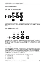
A party line telephone system consists of trunk path interconnecting several geographically
seperated stations and one or several local drops to subcriber telephone sets within a station.
The trunk path may consist of any combination of radio, pilot cable, microwave, fibre or power
line carrier links and may be designed in straight-line, star or ring configuration or any
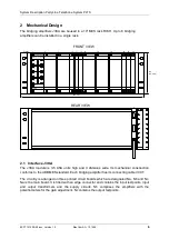
combination thereof. The described system consist of a 19” rack R7AH where bridging
amplifiers type J3KA can be installed. As a 4W telephone set a SETEL can be connected to
the bridging amplifiers. The SETEL is a 4-wire telephone set, with a selective DTMF number
decoder.
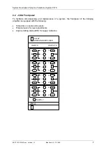
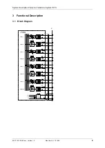
The bridging amplifier module J3KA serves as a combining unit for four 4-wire audio circuits. It
is well suited for speech as well as voice data party line applications.
Signals applied to an input of the J3KA are passed to all remaining outputs except its own.
Example: A signal applied to input 1 is passed to outputs 2, 3 and 4 but not to output 1.
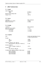
By means of twelve potentiometers the gain of any of these input to output paths can be
adjusted individually. Further, by means of jumpers, one of three coarse gain ranges can be
selected. The maximum voltage gains are as follows: low 6dB, medium 18dB, high 30dB.
Maximum output level is +16dBm when operated from a -48V supply or +10dBm when
operated from a -24V supply.
Inputs and outputs are 600
balanced, and are provided with interruptable testjacks.
Operation is from an unregulated DC supply of either -24 or -48V. The appropriate range can
be selected by means of a jumper. On the frontplate a green LED is provided for supply
indication.


