System Description Party Line Telephone System PLTS
BCPT1010.SD.E2.doc, Version 1.0
BlueCom AG, 1.3.1999
9
3.2 Typical Applications
3.2.1 Party Line Telephone System
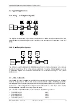
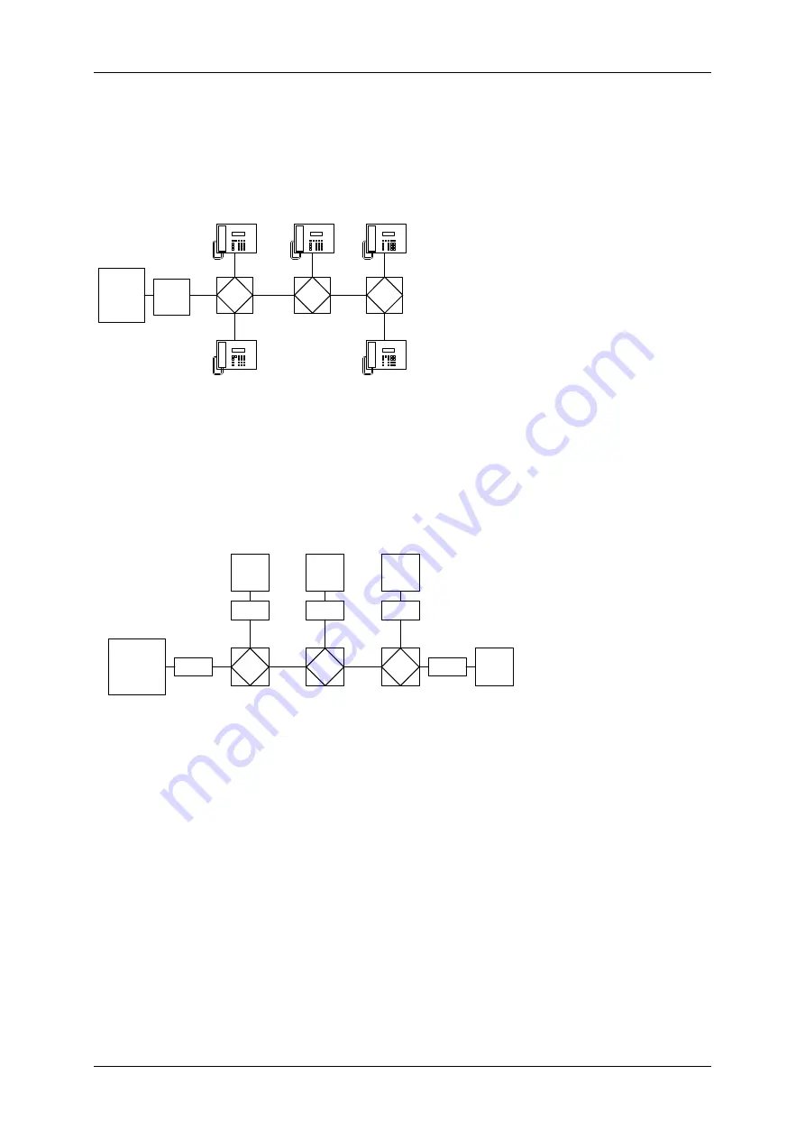
The diagram above shows a typical PLTS configuration. A PABX can be connected via its 4W
E&M interface to the PLTS system via a decoder. This decoder can be inserted in the rack
R7AH.
3.2.2 Data Party Line System
The J3KA are used to distribute the MODEM signal from the front end computer to the various
Remote Terminal Units (RTU) in the various substations. The same J3KA amplifiers are used
to collect the signals from the RTUs and transmit it to the front end computer in a system
control center.
3.3 J3KA Testpoints
Interruptible testpoints (U-links) are provided on all inputs and outputs which permit "bridged"
in-circuit measurements. The U-links can be removed which isolates the bridging amplifier
from the system and permits measurements on the wiring side or the bridging amplifier side.
To measure on the wiring side the testpoints to the left should be used. To measure on the
amplifier side the testpoints to the right should be used.
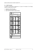
The testpoints are identified with a number and have the following functions:
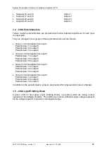
Testpoint 1 and 3
Input 1
Testpoint 4 and 6
Input 2
Testpoint 7 and 9
Input 3
Testpoint 10 and 12
Input 4
J3KA
J3KA
J3KA
DTMF
Decoder
PABX
SETEL
SETEL
SETEL
SETEL
SETEL
J3KA
J3KA
J3KA
MODEM
Front End
Computer
MODEM
RTU
MODEM
RTU
MODEM
RTU
RTU
MODEM


