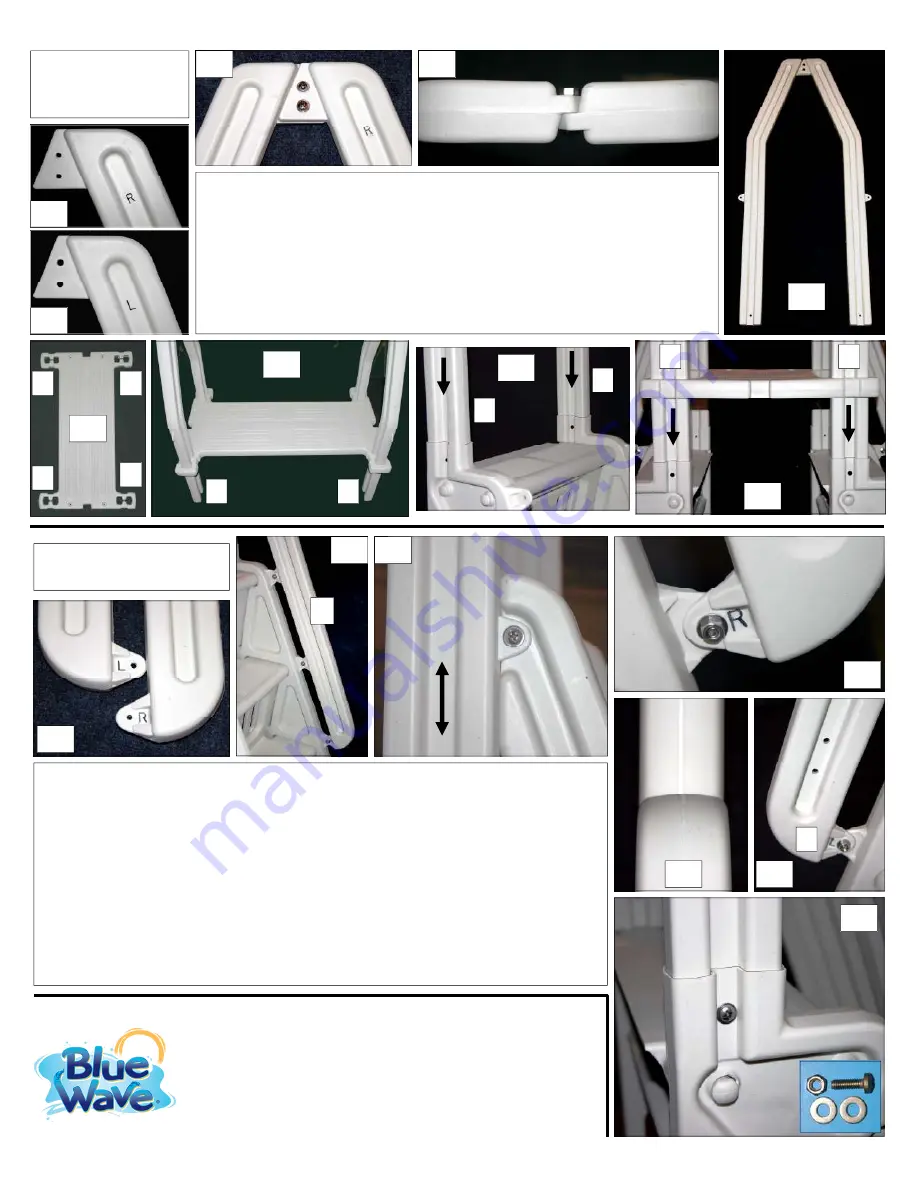
Step 6: FIT & SECURE
LOWER HANDRAILS
6.1
R
6.2
6.3
IN
LINE
6.6
Identify the lower RIGHT & LEFT handrails (small stamp in parts - Detail 6.1). Note: both the
lower left handrails have holes in the center; the holes are for connecting the gate in a later
step. Facing step as if the climb, position right handrail on the right side and left on the left
side. The lower handrails are to be positioned on the inside of the bolt flanges of the stringers
and upper handrails. Align the bolt flanges on the handrails with the bolt flanges on the
stringers and upper handrails (see Detail 6.2-6.5). When securing with hardware, it is
important to start with the connection point with the upper handrail (Detail 6.3). With the
lower handrail on the inside of the bolt flange, align bolt holes by sliding the upper handrail up
or down (Detail 6.3). Once aligned, make certain the upper and lower handrails are perfectly
aligned (Detail 6.6). Secure connection using 3/4" bolt, washer both sides and nut. Repeat for
all connection points on all lower handrails at all bolt flanges. After all handrails secured,
secure upper handrails with step stringers using same hardware (Detail 6.7). Drill a 5/16" hole
if bolt holes do not perfectly align. Repeat for all upper handrails and stringers
Step 5: ASSEMBLE
AND FIT UPPER
HANDRAILS
Identify the upper RIGHT (R) & LEFT (L) handrails (small stamp in parts - see Detail
5.1 & 5.2). Fit handrail pair together as shown in Detail 5.3 - 5.5 aligning bolt holes at
top. Secure using 1" bolts, washers both sides and nuts. Tighten hardware. Repeat
for both sets of upper handrails. Identify the top platform and with the anti-skid
surface facing up, fit the handrail pairs through the platform as shown in Detail 5.6 &
5.7. NOTE: it is important that the correct handrails (L & R) fit through the holes in
the platform as indicated. Slide the handrails up the handrail pairs. Fit the assembled
handrails pairs & top platform into the top openings of each step system (see Detail
5.8 & 5.9). Make certain they are positioned properly. DO NOT secure with hardware
5.1
5.2
5.3
RIGHT
LEFT
5.4
5.5
5.8
5.9
R
L
L
R
6.4
6.5
L
6.7
R
L
5.7
L
R
L
R
5.6
Blue Wave Products, Inc.
1745 Wallace Ave, Suite B
Saint Charles, IL 60174
Toll Free: 1-877-977-6010


