


507324-01B
Page 28 of 32
Issue 1809
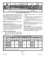
Unit
CO
2
% for Nat
CO
2
% for LP
-045
7.2 - 7.8
7.5 - 9.0
-070
-090
-110
Table 11.
High Altitude
This furnace is carefully designed for optimal performance
under a wide range of operating conditions. To ensure
proper operation at higher altitudes, certain adjustments
and/or kits may be required.
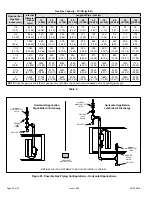
Manifold Pressure
Between 2000 and 7500 ft, certain units require manifold
pressure adjustments specified in Table 9. Manifold
pressure should be measured, and adjusted as required
during unit start up.
NOTE:
LP/Propane installations require a gas conversion
Orifice Kit as specified in Table 10.
Pressure Switch
Between 4501 and 7500 ft, some units may require a
pressure switch change. Table 10 lists the available
Pressure Switch Kits providing the minimum allowable
pressure switch set points, in this altitude range, for each
unit. The need for a Pressure Switch Kit may be evaluated
by comparing the pressure measured at the pressure
switch under steady state conditions (after 15 minutes of
run time) against the as shipped switch set point. Insufficient
negative pressure may lead to nuisance pressure switch
trips and possible unit lock outs.
Above 7500 feet, all units require both a burner orifice
change and a pressure switch change per Table 10.
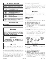
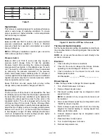
Fan Control
The fan on time of 45 seconds is not adjustable. The heat
fan off delay (amount of time that the blower operates after
the heat demand has been satisfied) may be adjusted by
changing the jumper position across the five pins on the
integrated control. The unit is shipped with a factory fan
off delay setting of 90 seconds. The fan off delay affects
comfort and is adjustable to satisfy individual applications.
Adjust the fan off delay to achieve a supply air temperature
between 90° and 110° F at the moment that the blower
is de-energized. Longer off delay settings provide lower
return air temperatures; shorter settings provide higher
return air temperatures. See Figure 35.
Figure 35. Heat Fan Off Time in Seconds
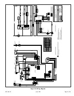
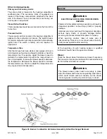
Thermostat Heat Anticipation
Set the heat anticipator setting (if adjustable) according to
the amp draw listed on the wiring diagram that is attached
to the unit.
NOTE:
Do not secure the electrical conduit directly to the
air ducts or structure.
Electrical
1. Check all wiring for loose connections.
2. Check for the correct voltage at the furnace (furnace
operating). Correct voltage is 120VAC ± 10%.
3. Check amp-draw on the blower motor with inner
blower panel in place.
Unit Nameplate__________ Actual _______________
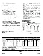
Blower Speeds
Follow the steps below to change the blower speeds.
1. Turn off electrical power to furnace.
2. Remove blower access panel.
3. Disconnect existing speed tap at integrated control
speed terminal.
NOTE:
Termination of any unused motor leads must
be insulated.
4. Place unused blower speed tap on integrated control
“PARK” terminal or insulate.
5. Refer to blower speed selection chart on unit wiring
diagram for desired heating or cooling speed. See
Blower performance data.
6. Connect selected speed tap at integrated control
speed terminal.
7. Resecure blower access panel.
8. Turn on electrical power to furnace.
9. Recheck temperature rise.