Blue Summit BG801UH Скачать руководство пользователя страница 15

507324-01B

Page 15 of 32

Issue 1809

If type B1 double wall vent is used inside a chimney, no 

other appliance can be vented into the chimney. The outer 

wall  of  type  B1  vent  pipe  must  not  be  exposed  to  flue 

products. A type B1 vent or masonry chimney liner shall 

terminate above the roof surface with a listed cap or a listed 

roof  assembly  according  to  the  terms  of  their  respective 

listings and the vent manufacturer’s instructions.

When  inspection  reveals  that  an  existing  chimney  is  not 

safe for the intended purpose, it shall be rebuilt to conform 

to  nationally  recognized  standards,  lined  or  relined  with 

suitable materials, or replaced with a gas vent or chimney 

suitable  for  venting.  The  chimney  passageway  must  be 

checked periodically to ensure that it is clear and free of 

obstructions.

Do not install a manual damper, barometric draft regulator, 

or flue restrictor between the furnace and the chimney.

Never connect a Category I appliance to a chimney that is 

servicing a solid fuel appliance. If a fireplace chimney flue 

is used to vent this appliance, the fireplace opening must 

be permanently sealed.

A  type  B1  or  listed  chimney  lining  system  that  passes 

through an unused masonry chimney flue is not considered 

to be exposed to the outdoors.

General Venting Requirements

Vent all furnaces according to these instructions:

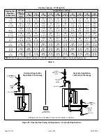
1.  Vent  diameter  recommendations  and  maximum 

allowable piping runs are found in the provided venting 

tables.

2.  In no case should the vent or vent connector diameter 

be  less  than  the  diameter  specified  in  the  provided 

venting tables.

3.  The minimum vent capacity determined by the sizing 

tables must be less than the low fire input rating and 

the maximum vent capacity must be greater than the 

high fire input rating.

4.  Single  appliance  vents  -  If  the  vertical  vent  or  tile 

lined chimney has a larger diameter or flow area than 

the vent connector, use the vertical vent diameter to 

determine  the  minimum  vent  capacity  and  the  vent 

connector  diameter  to  determine  the  maximum  vent 

capacity. The flow area of the vertical vent, however, 

shall  not  exceed  7  times  the  flow  area  of  the  listed 

appliance  categorized  vent  area,  drafthood  outlet 

area or flue collar area unless designed according to 

approved engineering methods.

5.  Multiple appliance vents - The flow area of the largest 

section of vertical vent or chimney shall not exceed 7 

times  the  smallest  listed  appliance  categorized  vent 

area, drafthood outlet area or flue collar area unless 

designed according to approved engineering methods.

6.  The entire length of single wall metal vent connector 

shall  be  readily  accessible  for  inspection,  cleaning, 

and replacement.

7.  Single appliance venting configurations with zero lateral 

lengths (Table 3) are assumed to have no elbows in 

the vent system. For all other vent configurations, the 

vent system is assumed to have two 90° elbows. For 

each additional 90° elbow or equivalent (for example 

two 45° elbows equal one 90° elbow) beyond two, the 

maximum  capacity  listed  in  the  venting  table  should 

be reduced by 10% (0.90 x maximum listed capacity).

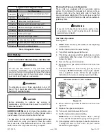
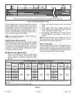
8.  The  common  venting  Table  4  and  Table  5  were 

generated using a maximum horizontal vent connector 

length of 1-1/2 feet (.46 m) for each inch (25 mm) of 

connector diameter as follows:

Table 2. 

Connector Diameter 

in. (mm)

Maximum Horizontal 

Connector Length 

ft. (m)

3 (76)

4-1/2 (1.37)

4 (102)

6 (1.83)

5 (127)

7-1/2 (2.29)

6 (152)

9 (2.74)

7 (178)

10-1/2 (3.20)

9.  If  the  common  vertical  vent  is  offset,  the  maximum 

common vent capacity listed in the common venting 

tables  should  be  reduced  by  20%,  the  equivalent 

of  two  90°  elbows  (0.80  x  maximum  common  vent 

capacity). The horizontal length of the offset shall not 

exceed  1-1/2  feet  (.46  m)  for  each  inch  (25  mm)  of 

common vent diameter.

10.  The  vent  pipe  should  be  as  short  as  possible  with 

the  least  number  of  elbows  and  angles  required  to 

complete the job. Route the vent connector to the vent 

using the shortest possible route.

11.  A vent connector shall be supported without any dips 

or  sags  and  shall  slope  a  minimum  of  1/4  inch  (6.4 

mm)  per  linear  foot  (305  mm)  of  connector,  back 

toward the appliance.

12.  Vent connectors shall be firmly attached to the furnace 

flue  collar  by  self  drilling  screws  or  other  approved 

means,except  vent  connectors  of  listed  type  B  vent 

material  which  shall  be  assembled  according  to  the 

manufacturer’s  instructions.  Joints  between  sections 

of  single  wall  connector  piping  shall  be  fastened  by 

screws or other approved means.

13.  When  the  vent  connector  used  for  Category  I 

appliances must be located in or pass through a crawl 

space,  attic  or  other  areas  which  may  be  cold,  that 

portion  of  the  vent  connector  shall  be  constructed 

of listed double wall type B vent material or material 

having equivalent insulation qualities.

Содержание BG801UH

Страница 1: ...Improper installation adjustment alteration service or maintenance can cause property damage personal injury or loss of life Installation and service must be performed by a licensed professional installer or equivalent service agency or the gas supplier WARNING As with any mechanical equipment personal injury can result from contact with sharp sheet metal edges Be careful when you handle this equi...

Страница 2: ...r filter 2 Single side return air with optional RAB Return Air Base 3 Bottom return air 4 Return air from both sides 5 Bottom and one side return air 2 Flue outlet may be horizontal but furnace must be vented vertically 3 Optional external side return air filter kit cannot be used with the optional RAB Return Air Base Consider sizing requirements for optional IAQ equipment before cutting side retu...

Страница 3: ... vestibule area In order to ensure proper unit operation combustion and ventilation air supply must be provided according to the current National Fuel Gas Code Vent installations must be consistent with the venting tables in this instruction and applicable provisions of local building codes This furnace is CSA International certified for installation clearances to combustible material as listed on...

Страница 4: ...ature rise must be set per the furnace rating plate e Supply and Return air ducts must be provided and sealed to the furnace Return air must be terminated outside of the space where furnace is installed f Return air temperature range between 60 F 16 C and 80 F 27 C must be maintained g MERV 11 or greater air filters must be installed in the system and must be regularly inspected and maintained e g...

Страница 5: ...fficient combustion air is not available the furnace or other appliances will operate inefficiently and unsafely Enough air must be provided to meet the needs of all fuel burning appliances and appliances such as exhaust fans which force air out of the house When fireplaces exhaust fans or clothes dryers are used at the same time as the furnace much more air is necessary to ensure proper combustio...

Страница 6: ...enclosure and one opening within 12 inches 305 mm of the bottom See Figure 2 Air from Outside If air from outside is brought in for combustion and ventilation the confined space must have two permanent openings One opening shall be within 12 inches 305 mm of the top of the enclosure and one opening within 12 inches 305 mm of the bottom These openings must communicate directly or by ducts with the ...

Страница 7: ... back of the furnace Doing so will adversely affect the operation of the safety control devices which could result in personal injury or death WARNING The gas furnace can be installed as shipped in either the upflow position or the horizontal position Select a location that allows for the required clearances that are listed on the unit nameplate Also consider gas supply connections electrical supp...

Страница 8: ...e and the platform to ensure that the furnace operates properly and safely The furnace is equipped with a removable bottom panel to facilitate installation Markings are provided on both sides of the furnace cabinet for installations that require side return air Cut the furnace cabinet at the maximum dimensions shown on Page 2 NOTE 20C and 20D units that require air volumes over 1800 cfm 850 L s mu...

Страница 9: ... and supply and return air plenums must be supported separately NOTE When the furnace is installed on a platform in a crawlspace it must be elevated enough to avoid water damage and to allow the evaporator coil to drain Figure 11 Optional Return Air Base Upflow Applications Only For use with A B C and D cabinets FRONT VIEW 1 Unit side return air Opening SIDE VIEW 3 1 4 83 1 23 584 Overall Maximum ...

Страница 10: ... living space Use screws and joint tape to seal the return air system to the furnace Inplatforminstallationswithbottomreturnair thefurnace should be sealed airtight to the return air plenum A door must never be used as a portion of the return air duct system The base must provide a stable support and an airtight seal to the furnace Allow absolutely no sagging cracks gaps etc The return and supply ...

Страница 11: ...hout the house by the furnace duct system In upflow applications the return air can be brought in through the bottom or either side of the furnace If a furnace with bottom return air is installed on a platform make an airtight seal between the bottom of the furnace and the platform to ensure that the unit operates properly and safely Use fiberglass sealing strips caulking or equivalent sealing met...

Страница 12: ...h hose from barbed fitting on the pressure switch assembly Remove pressure switch assembly 1 screw and cut wire tie to free pressure switch wires Reinstall pressure switch on the other side of orifice plate and reconnect pressure switch hose Resecure pressure switch wires Either pull excess wires through the blower compartment and secure using supplied wire tie or coil excess wire and secure to th...

Страница 13: ...on instructions and the provided venting tables in these instructions The venting tables in this manual were extracted from the National Fuel Gas Code NFPA 54 ANSI Z223 1 and are provided as a guide for proper vent installation Proper application termination construction and location of vents must conform to local codes having jurisdiction In the absence of local codes the NFGC serves as the defin...

Страница 14: ...ot accommodate a listed metal liner either the chimney must be rebuilt to accommodate one of these liners or an alternate approved venting method must be found Insulation for the flexible vent pipe must be an encapsulated fiberglass sleeve recommended by the flexible vent pipe manufacturer SINGLE appliance venting of a fan assisted furnace into a tile lined masonry chimney interior or outside wall...

Страница 15: ...appliance vents The flow area of the largest section of vertical vent or chimney shall not exceed 7 times the smallest listed appliance categorized vent area drafthood outlet area or flue collar area unless designed according to approved engineering methods 6 The entire length of single wall metal vent connector shall be readily accessible for inspection cleaning and replacement 7 Singleappliancev...

Страница 16: ...acity listed in the common venting tables must be reduced by 10 the equivalent of one 90 elbow 0 90 x maximum common vent capacity 18 The common vent diameter must always be at least as large as the largest vent connector diameter 19 In no case shall the vent connector be sized more than two consecutive table size diameters over the size of the draft hood outlet or flue collar outlet 20 Do not ins...

Страница 17: ...9 15 136 20 226 22 339 5 22 65 30 130 39 219 49 330 10 29 59 40 121 51 206 64 315 15 35 53 48 112 61 195 76 301 20 0 0 97 0 202 0 349 0 540 2 10 75 14 149 18 250 20 377 5 21 71 29 143 38 242 47 367 10 28 64 38 133 50 229 62 351 15 34 58 46 124 59 217 73 337 20 48 52 55 116 69 206 84 322 30 0 0 100 0 213 0 374 0 587 2 9 81 13 166 14 283 18 432 5 21 77 28 160 36 275 45 421 10 27 70 37 150 48 262 59 ...

Страница 18: ... 220 15 1 21 50 33 89 47 142 64 220 2 22 53 35 96 49 153 66 235 3 24 55 36 102 51 163 68 248 20 1 21 54 33 99 46 157 62 246 2 22 57 34 105 48 167 64 259 3 23 60 35 110 50 176 66 271 30 1 20 62 31 113 45 181 60 288 2 21 64 33 118 47 190 62 299 3 22 66 34 123 48 198 64 309 Table 4 Common Vent Capacity Type B Double Wall Vents with Type B Double Wall Connectors Serving Two or More Category I Applianc...

Страница 19: ...ance connected to the common venting system is venting properly step 3 return all doors windows exhaust fans fireplace dampers and any other gas burning appliances to their previous mode of operation 7 If a venting problem is found during any of the preceding tests the common venting system must be modified to correct the problem Resize the common venting system to the minimum vent pipe size deter...

Страница 20: ... 20 930 360 10 19 250 7 08 200 5 66 170 4 81 151 4 28 138 3 91 125 3 54 118 3 34 110 3 11 103 2 92 1 25 4 1 049 26 645 680 19 25 465 13 17 375 10 62 320 9 06 285 8 07 260 7 36 240 6 80 220 6 23 205 5 80 195 5 52 1 1 4 31 75 1 380 35 052 1400 39 64 950 26 90 770 21 80 660 18 69 580 16 42 530 15 01 490 13 87 460 13 03 430 12 18 400 11 33 1 1 2 38 1 1 610 40 894 2100 59 46 460 41 34 1180 33 41 990 28...

Страница 21: ...ures Electrostaticdischargecanaffectelectroniccomponents Take precautions during furnace installation and service to protect the furnace s electronic controls Precautions will help to avoid control exposure to electrostatic discharge by putting the furnace the control and the technician at the same electrostatic potential Neutralize electrostatic charge by touching hand and all tools on an unpaint...

Страница 22: ... control See for integrated control configuration This terminal is energized when the indoor blower is operating Any accessory rated up to one amp can be connected to this terminal with the neutral leg of the circuit being connected to one of the provided neutral terminals If an accessory rated at greater than one amp is connected to this terminal it is necessary to use an external relay One line ...

Страница 23: ...507324 01B Page 23 of 32 Issue 1809 045AP12 110CP20 110CP16 090BP16 070AP12 Figure 30 Wiring Diagram ...

Страница 24: ...mostat is set to FAN ON the indoor blower will run continuously on the heating speed when there is no cooling or heating demand 2 When the unit is running in the heating mode the indoor blower will run on the heating speed 3 When there is a cooling demand the indoor blower will run on the cooling speed NOTE This control is equipped with a push button switch for diagnostic code recall The control s...

Страница 25: ...l injury or death WARNING Gas Valve Operation See Figure 33 1 STOP Read the safety information at the beginning of this section 2 Set the thermostat to the lowest setting 3 Turn off all electrical power to the unit 4 This furnace is equipped with an ignition device which automatically lights the burners Do not try to light the burners by hand 5 Remove the upper access panel 6 Move switch on gas va...

Страница 26: ...4 After a 20 second ignitor warm up period the gas valve solenoid opens A 4 second trial for ignition period begins 5 Gas is ignited flame sensor proves the flame and the combustion process continues 6 If flame is not detected after first ignition trial the ignition control will repeat steps 3 and 4 four more times before locking out the gas valve The ignition control will then automatically repea...

Страница 27: ...nd remove manometer as soon as an accurate reading has been obtained Take care to remove barbed fitting and replace threaded plug Proper Combustion Furnace should operate a minimum 15 minutes with correct manifold pressure and gas flow rate before checking combustion Take combustion sample beyond the flue out let and compare to the tables below The maximum carbon monoxide reading should not exceed...

Страница 28: ...umper position across the five pins on the integrated control The unit is shipped with a factory fan off delay setting of 90 seconds The fan off delay affects comfort and is adjustable to satisfy individual applications Adjust the fan off delay to achieve a supply air temperature between 90 and 110 F at the moment that the blower is de energized Longer off delay settings provide lower return air t...

Страница 29: ...an be drawn into living space resulting in personal injury or death WARNING Other Unit Adjustments Primary and Secondary Limits The primary limit is located on the heating compartment vestibule panel The secondary limits if equipped are located in the blower compartment attached to the back side of the blower These auto reset limits are factory set and require no adjustment Flame Rollout Switches ...

Страница 30: ...ecommended filter sizes Flue and Chimney 1 Check flue pipe chimney and all connections for tightness and to make sure there is no blockage 2 Check unit for proper draft Electrical 1 Check all wiring for loose connections 2 Check for the correct voltage at the furnace furnace operating Correct voltage is 120VAC 10 3 Check amp draw on the blower motor with inner blower panel in place Unit Nameplate_...

Страница 31: ...45 942 Med 1137 1131 1102 1080 1037 977 913 828 Low 958 956 943 925 879 837 777 725 090BP16 1 2 4 spd 10 x 10 30 60 High 1911 1840 1770 1663 1584 1469 1357 1198 Med High 1738 1707 1634 1560 1468 1364 1232 1121 Med 1533 1502 1462 1408 1329 1262 1157 1019 Low 1303 1304 1281 1225 1192 1116 1018 918 110CP16 1 2 4 spd 10 x 10 30 60 High 2078 2017 1939 1848 1775 1679 1559 1425 Med High 1791 1746 1693 16...

Страница 32: ...m height of eight 8 feet above grade directly in line with the exhaust vent terminal for the horizontally vented gas fueled heating appliance or equipment The sign shall read in print size no less than one half 1 2 inch in size GAS VENT DIRECTLY BELOW KEEP CLEAR OF ALL OBSTRUCTIONS 4 INSPECTION The state or local gas inspector of the side wall horizontally vented gas fueled equipment shall not app...

Отзывы: