-24-
Revision 3/F3542
Two
Screws
Two
Screws
Two Screws
6.3.6 BAKE TIMER
1) Remove bake timer knob by pulling it
firmly away from control panel.
2) Open control panel (refer 6.2.1) and undo
two screws securing timer.
Fan Element
Three Screws
Top Element
Two Screws
6.3.9 ELEMENT
6.3.7 THERMOSTAT
1) Pull knob off front of thermostat
2) Open control panel (refer 6.2.1) and undo
two screws securing thermostat.
3) Transfer wires to new timer.
4) Withdraw old timer and insert new timer,
securing with screws.
5) Replace knob.
Two Screws
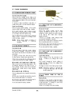
Figure 6.3.6
5) Withdraw old thermostat phial through
rear of oven.
6) Insert new thermostat.
7) Re-assemble in reverse order.
3) Transfer wires to new thermostat.
4) Remove service panel (refer 6.2.2) and
from inside of oven loosen two screws
holding thermostat phial bracket.
Figure 6.3.7
Figure 6.3.8
1) With service panel and baffle removed
(refer 6.2.2 and 6.2.3) remove the wires
from the element(s).
2) Unscrew the element from inside the
oven.
3) Pull element carefully to remove.
4) Replace and re-assemble in reverse
order.
Figure 6.3.10
Element Ratings
100-120V
Top Element
7.2 ohms
Fan Element (E25)
9.3 ohms
220-240V
Fan Element
28.8 ohms
Fan Element (E25B) 7.2 ohms
6.3.8 RELAY
1) Remove service panel (refer 6.2.2).
2) Undo two screws securing relay to oven.
Figure 6.3.9
3) Transfer wires to new relay, and secure to
oven with screws.
Broil
Relay
Heating
Relay
Содержание E25
Страница 1: ... 1 Revision 3 F3542 SERVICE MANUAL E25 CONVECTION OVEN ...
Страница 30: ... 30 Revision 3 F3542 7 ELECTRICAL CIRCUIT SCHEMATIC 7 1 E25 ...
Страница 31: ... 31 Revision 3 F3542 7 2 E25B ...
Страница 32: ... 32 Revision 3 F3542 8 ELECTRICAL WIRING DIAGRAM 8 1 E25 ...
Страница 33: ... 33 Revision 3 F3542 8 2 E25B ...
Страница 36: ... 36 Revision 3 F3542 11 PARTS DIAGRAMS 11 1 MAIN ASSEMBLY E25 ...
Страница 38: ... 38 Revision 3 F3542 11 2 MAIN ASSEMBLY E25B 110V ONLY ...
Страница 46: ... 46 Revision 3 F3542 ...


