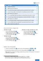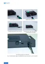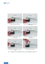
Robot flange
1
Cylinder pin
1
(optional)
9
2
11
2
Allen key
1
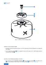
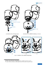
(a) Installation of the robot flange adapter
9
2
11
2
7
8
10
3
Allen key
1
(b) Installation of the AIRSKIN® Safetyflange on the robot
7
10
3
(c)
8
10
3
(d)
(e)
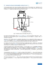
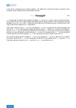
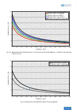
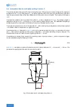
Fig. 6.2: Installation of the AIRSKIN® Safetyflange.
1
Component is not included in the scope of delivery.
2
The scope of delivery includes the robot adapter plate that is supplied for the specific customer.
3
The scope of delivery includes the tool flange adapter plate that is supplied for the specific customer.
Содержание AIRSKIN
Страница 1: ...SAFETYFLANGE OPERATING MANUAL 2020 06 30 v1 2 English Translation...
Страница 17: ...A A A A 135 5 1 63 13 0 5 82 5 89 0 5 Fig 3 3 Dimensions of the AIRSKIN Safety ange in mm 13 62...
Страница 25: ...1 2 3 Plain Bearing Washer 1 5 4 6 3 Plain Bearing Washer 2 7 Fig 4 4 Exchanging the spring 21 62...
Страница 57: ...1 2 3 Plain Bearing Washer 1 5 4 6 3 Plain Bearing Washer 2 7 Fig 10 2 53 62...
Страница 66: ...15 Declaration of Conformity and manufacturer 62 62...

