background image

BWOS 30100 SERVICE MANUAL 

21 

3.3.1 Flashing Symbols or Numbers 

Signals an incomplete setting and calls for another input. 


3.3.2 Beeps 

Signals that more information must be entered or confirms the receipt of an entry. Beeps 
also signal the end of a function or an oven fault. 


3.3.3 Fast Preheat 

Whenever the oven must heat rapidly, turn the cooking mode selector to fast preheat 
position. As soon as the preheat tone is sounded and the red light turns off, select the 
desired cooking mode and put food inside. 


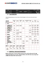
3.3.4 Lock Symbol 

It’s displayed when the door is locked, during the Self-Clean mode or following cooling 
down. The symbol flashes when the latch is moving to lock or unlock the door. Do not 
attempt to open the door. Door can be opened when the symbol no longer appears. 


3.3.5 Safety Door Lock 

The door latch mechanism is not used only to lock the door in self-clean but also to lock 
the door manually for safety reason (prevent children from getting in touch with hot 
parts) during ordinary cooking activities. 

Single oven: hold at the same time for 3 seconds INC (+) and LOCK keys. The latch will 
lock the door. Repeat the same operation to unlock. 


3.3.6 Power Failure 

After the power returns to the oven, the clock displays the time 12.00


Содержание 8978983800

Страница 1: ...RVIEW 2 1 OVEN SPECIFICATIONS 2 1 1 Oven Weight 2 1 2 Power Rating 2 2 SERIAL PLATE 2 2 1 Location 2 2 2 Model and Serial Number 2 3 COMPONENT SPECIFICATIONS 2 3 1 Heating Elements 2 3 2 Motors 2 3 3...

Страница 2: ...mbol 3 3 5 Safety Door Lock 3 3 6 Power Failure 3 3 7 Default Settings 3 3 8 F Failure Number Codes 3 3 9 Convection Fan 3 3 10 Component Cooling Fan 3 4 SETTING THE CLOCK AND TIMER 3 4 1 To Set the C...

Страница 3: ...HE SELF CLEANING 3 9 1 To set the Self Clean Mode 3 9 2 To change the Clean Time 3 9 3 To Delay the Start of Clean 3 10 OVEN DOOR REMOVAL 3 10 1 To Remove Door 3 10 2 To Replace Door 3 11 REPLACING AN...

Страница 4: ...ENT SUBSTITUTION 7 7 LOWER ELEMENT SUBSTITUTION 7 8 LOCK DOOR MOTOR SUBSTITUTION 7 9 LOCK DOOR MOTOR SWITCH SUBSTITUTION SOLUTION 7 10 LOOK DOOR SWITCH SUBSTITUTION 7 11 DOOR GASKET SUBSTITUTION 7 12...

Страница 5: ...ault finding then extreme care should be taken not to make contact with electrical components other than with testing probes Ensure the oven is turned off when removing any electrical component or con...

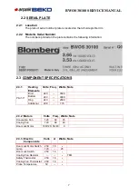
Страница 6: ...ital power meter Voltage Current Static strap 2 TECHNICAL OVERVIEW 2 1 OVEN SPECIFICATIONS 2 1 1 Oven Weight Single 30 lbs Kg 148 67 2 1 2 Power rating TECHNICAL DATA OVENS Electrical Ratings and Maxi...

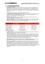
Страница 7: ...Note Piro 30 Broil 240 3500 Bottom 240 3000 Ring 240 2500 Additional 208 775 2 3 2 Motors Volts Freq Watts Note Convection Fan 120 60 45 Cooling Fan 120 60 40 Door Lock Motor 100 120 50 60 3 2 3 3 El...

Страница 8: ...IONAL ELEMENT 775W at 208V meaning 1032W at 240V NOT AVIABLE CONVECTION FAN This fan is available in multifunction cavities it works always at the same speed in all convection modes self clean and deh...

Страница 9: ...5 seconds Press to enter test mode then press to get into the next step Press to come back to the previous one Check the display board SOFTWARE VERSION d40 Check the main power board SOFTWARE VERSION...

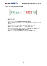
Страница 10: ...the control displays tESt Always press button to proceed to the following step Verify the software versions of display and power boards Verify that the oven model has been correctly detected by the c...

Страница 11: ...04 check that no heating elements are energized The double line break relay must be open S05 bottom element 3000W 240v 12 5 2253W 208v 10 8A S06 top element 3500W 240v 14 6 2629W 208v 12 6 S07 ring el...

Страница 12: ...ob clockwise and check that the values correspond to the ones in the following table Code ENGLISH Multifunction C00 Off C01 Convection bake C02 Convection broil C03 Convection roast C04 Fast preheat C...

Страница 13: ...se and verify that the temperature changes between 170 f and 550 f Verify that in clean position the display shows tESt cln Once back in preset position the control shows automatically the step number...

Страница 14: ...ay shows Sele deg Hold then timer and stop time keys until the display gets completely dark then hold cook time and stop time further until the display shows Volt 240 Pressing set clock key again edit...

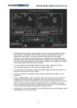
Страница 15: ...ion lines data clock and the voltages GND 5v The main power board to lower power board cable supports the same lines plus an additional 24v line for the relay voltage Each cable between the display bo...

Страница 16: ...Upper or single oven runaway temperature condition 950 F F07 Lower oven runaway temperature condition 950 F F08 Short circuit on display board microcontroller pins F09 Short circuit on display board F...

Страница 17: ...cavity an electronic sensor NTC or negative temperature coefficients mounted on the main power board see chapter 2 7 for more information The role of the NTC is to protect the electronic boards of an...

Страница 18: ...actory set up RPM rotation per minute 2 9 5 Safety Thermostat The function of the safety thermostat is to protect the of the oven from over heating in the event of a malfunction of the cooling fan Des...

Страница 19: ...to decrease the value of the currently selected variable 3 1 2 Display Preheat light external Four time digits green for time of day minute minder automatic cooking AM PM indication is also present T...

Страница 20: ...0 F 450 F 550 F 4 BAKE No 12 60 40 60 8 60 170 F 350 F 550 F 5 BROIL No LEVE L Leve l 1 Leve l 3 Leve l 5 6 CLEAN 208V Yes 43 60 12 60 100 5 60 887 F 6 CLEAN 240V Yes 43 60 12 60 5 60 887 F 7 FAST PRE...

Страница 21: ...Symbol It s displayed when the door is locked during the Self Clean mode or following cooling down The symbol flashes when the latch is moving to lock or unlock the door Do not attempt to open the doo...

Страница 22: ...t time 3 3 10 Component Cooling Fan Activates during any cooking or self cleaning mode to cool inner components and outer door surfaces This air is exhausted through the vent located above the oven do...

Страница 23: ...the desired hour Continue until correct AM or PM is selected 3 Press Set Clock again to confirm the hour and minutes will start flashing 4 Press or to set the desired minutes value hold the key to cha...

Страница 24: ...will be steadily displayed 8 When the time ends reminder beeps will sound for 15 minutes or until the key is pressed 9 Timer format is usually HR MIN but it switches to MIN SEC during the last minute...

Страница 25: ...as preheated it will beep and switch the red light off To change the temperature while cooking simply turn the temperature knob until the display shows the desired value Move the cooking mode selector...

Страница 26: ...gits will begin flashing 5 Press or to change the hours Keep in mind that the time required for the oven to reach temperature must be included in the set cooking time 6 Press Cook Time again hours wil...

Страница 27: ...or 5 seconds 10 Example if the timer value is displayed press cook time key to view the cook time for 5 seconds 11 Timer value is displayed when both timer and cook time are running 3 7 SPECIAL FEATUR...

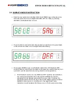
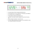
Страница 28: ...keys to set Sabbath mode ON or OFF Default OFF Press CLOCK to confirm and come back to the option list Hold CLOCK key for 3 seconds to quit the selection menu and go back to normal operations Once Sab...

Страница 29: ...an be displayed The cooling fan must run in Sabbath mode Preheat lights are inhibited during Sabbath mode The buzzer must always be silent regardless of any fault end of activity etc Maximum allowed c...

Страница 30: ...ll not open before starting Self Clean mode If door does not lock rotate the cooking mode knob into OFF position and do not start self clean phone for service If the door is in the open position when...

Страница 31: ...off 11 End will appear on the display CLEAN TIME will flash until any time key is touched or the knob is moved to OFF position TO CHECK CLEAN TIME OR STOP TIME during a delayed clean simply press COO...

Страница 32: ...he lens by unscrewing it 5 Remove the light bulb from its socket by pulling it 6 Replace the bulb with a new one Avoid touching the bulb with fingers as oils from hands can damage the bulb when it bec...

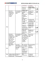
Страница 33: ...ITIONS RESPECTIVELY Code Error Description Possible Cause Corrective Action section F01 Temperature sensor The control reads out of range values Temperature sensor shorted or broken Replace the sensor...

Страница 34: ...ailure Humidity may have created condensation on the circuits Remove power and dry the board Short circuit on display board Replace the display board 7 19 F10 Possible short circuit on display board c...

Страница 35: ...he main power board 7 17 Faulty ntc sensor on main power board Replace the main power board 7 17 Electronic boards over temperature in a double oven t 105 c to stop only the lower one when the upper i...

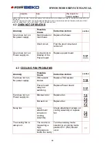
Страница 36: ...circuit and remove it Oven does not run Power supply ok Connections to Display or the Power board Replace power board 7 17 4 3 COOLING FAN PROBLEMS Anomaly Possible Cause Corrective Action section Fa...

Страница 37: ...d rotor Replace fan 7 4 Burned coil Replace fan 7 4 Noisy fan Lose attachment screws on cooling assembly Check attachment screws Check nut on working fan for tightness or replace it 4 5 DOOR LOCK PROB...

Страница 38: ...damaged replace it 7 14 Check the power board If is damaged replace it 7 17 The Oven had been locked by means of the child lock procedure Use the same procedure to unlock the door 3 3 The control doe...

Страница 39: ...Every cooking mode accepts only the preset temperature and clean will not start The control cannot read the temperature selector Check the connections between the selectors and the display board Check...

Страница 40: ...k and eventually replace the main power board 7 17 During the manual test it s not possible to check the software version of one board The displays shows d or p without any number The board has never...

Страница 41: ...er on the heating elements check relays on the power boards If the power board relay not switching replace the units 7 17 Check the power on the heating elements and replace the elements if needed 7 5...

Страница 42: ...BWOS 30100 SERVICE MANUAL 42 5 ELECTRIC DIAGRAM 5 1 SINGLE OVEN MULTIFUNCTION...

Страница 43: ...BWOS 30100 SERVICE MANUAL 43 6 EXPLODED PARTS 6 1 SINGLE OVEN 30...

Страница 44: ...BWOS 30100 SERVICE MANUAL 44...

Страница 45: ...BWOS 30100 SERVICE MANUAL 45...

Страница 46: ...BWOS 30100 SERVICE MANUAL 46...

Страница 47: ...BWOS 30100 SERVICE MANUAL 47...

Страница 48: ...BWOS 30100 SERVICE MANUAL 48...

Страница 49: ...9 7 COMPONENT REPLACEMENT AND ADJUSTMENT PROCEDURE 7 1 OVEN REMOVAL 1 Disconnect the power supply cord 2 Remove the screws shown in the pictures 3 Pull off the oven 4 Remove the oven by using the late...

Страница 50: ...ws on the attachment bar four lateral three on the top 4 Disconnect the terminals on the fan 5 Remove the four screws on the fan and remove the fan 6 During mounting of the new cooling fan motor you m...

Страница 51: ...BWOS 30100 SERVICE MANUAL 51 10 Reconnect the power supply cord after the Oven is installed 11 Run the Oven and check all functions 7 3...

Страница 52: ...n the fan in the rear side 6 Remove the four screws with spacers on the motor holder and remove it Than to remove the motor from the holder use a 12mm socket 7 Mount the new fan motor on the holder an...

Страница 53: ...ble the baffle by removing the four screws in the cavity 5 Remove the ring element by removing the three screws 6 Mount the new ring element with the new fiber gasket between the base of the element a...

Страница 54: ...s one of which is used for ground 5 Remove the upper element by removing two screws on the brackets on top in the cavity 6 Mount the new upper element with a new fiber gasket between the base of the e...

Страница 55: ...ear the external terminals and the other four on the brackets 5 Remove the brackets 6 Pull out the lower element 7 Replace the new element by reversing the previous steps 8 Pay attention to the positi...

Страница 56: ...mounted on Lower cavity of Double Oven remove the lateral screws and pull up the motor 7 Disassemble the motor by removing the two screws and remove also the brackets 8 Replace the new by reversing t...

Страница 57: ...ve the micro switch by the two screws 4 Replace the new switch by reversing the previous steps see section 7 8 Pay attention when positioning and inserting the door lever mechanism into the wheel of t...

Страница 58: ...e middle panel to reach it 3 Disconnect the terminals from the switch 4 Unscrew the bracket 5 Pull out the switch from the holder 6 Replace with a new switch by reversing the previous steps 7 PAY ATTE...

Страница 59: ...BWOS 30100 SERVICE MANUAL 59 7 11 DOOR GASKET SUBSTITUTION 1 Open door and pull out the gasket by hands 2 Replace with a new switch by reversing the previous steps...

Страница 60: ...from the cabinet 2 Remove the upper or rear covers Remove the resistor screws 3 Replace with a new resistor by reversing the previous steps 4 The connections must not be loose 5 Reinstall the Oven int...

Страница 61: ...r upper cavity For lower cavity remove rear cover and the middle panel in front for the lower cavity 3 Unscrew the thermostat 4 Replace with a new thermostat by reversing the previous steps 5 The conn...

Страница 62: ...from the cabinet 2 Remove the rear covers 3 To replace the probe disconnect it and remove the attachment screws 4 During operation the ceramic fiber must be around the probe hole 5 Reinstall the Oven...

Страница 63: ...th a soft cloth to prevent scratching of the aesthetics 3 Unscrew the door glass 4 Remove the hinges following 5 To replace the hinges reverse the previous steps 6 To replace the aesthetic glass be su...

Страница 64: ...nscrew the boxes to change support 4 Disassembling the hinges box 5 To replace the new hinge box reverse the previous steps During the mounting of the box the wheels will be in a high position 6 Repla...

Страница 65: ...the new power board using the spacers 5 Connect the cable following the electric diagram 6 IT IS VERY IMPORTANT TO CONNECT THE CABLES IN THE RIGHT POSITION 7 The connections must not be loose 8 Recon...

Страница 66: ...over 3 Remove the knobs and the glass 4 Disconnect the bad selector and remove it by the screws 5 Replace the new selector by reversing the previous steps 6 DURING MOUNTING THE SPRING BUTTONS MUST BE...

Страница 67: ...knobs and the glass 4 Disconnect the bad display board and remove it by the nylon spacers 5 BEFORE REPLACING THE UNIT CUT THE RESISTOR FOR OVEN CONFIGURATION FOLLOWING THE TABLE ON SECTION 2 5 6 Rein...

Страница 68: ...from the door unscrewing two screws on the corner and three screws on the bottom 4 Remove also the handle by its two screws 5 Replace the handle on the new aesthetic glass with its support and spacer...

Страница 69: ...emove also all the fiber insulation 5 Now depends which glasses is broken if it s the central one disassembling the metal frame which fix the glass and replace with the new one if is one of the extern...

Страница 70: ...BWOS 30100 SERVICE MANUAL 70...

Отзывы: