


11
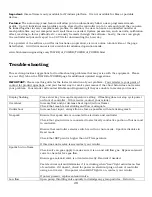
Note:
Depending on the gas supply you have, you may need to procure additional or different fittings which
are not included with the product. In ALL cases, follow your local codes and regulations. If you are not
familiar with the local requirements, or are not comfortable doing this work yourself, we would recommend
hiring a professional to do this for you.
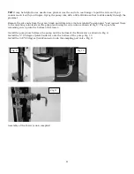
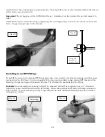
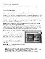
Fig 16 shows a typical installation. Note that it is permissible to install the solenoid valve immediately after
the regulator on the propane tank.
Important!
Valve failures from excessive heat are not covered under warranty!
Warning!
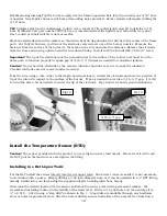
Install the valve with the gas flow going in the direction of the arrow marked on the valve. Fig 15.
Installing it backwards can result in poor and/or unsafe operation! The inlet will also be marked with a “1”
and the outlet with a “2”.
Warning!
DO NOT use the solenoid valve as a normal shutoff for the gas! ALWAYS turn the propane tank or
gas valve off at the source when not in use!
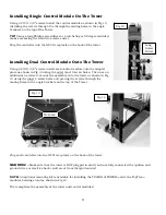
Fig 16 and 17 show typical installations.
Important:
The brass orifice fitting (small hole
through it) supplied with your burner must ALWAYS be
installed directly on the burner casting. Do NOT install
this fitting on the inlet to the regulator or your burner
will not function properly!
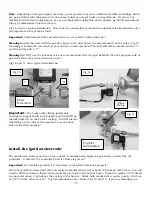
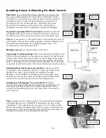
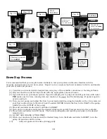
Install the ignition electrode:
The ignition electrode is used to create a spark to automatically ignite the gas and is activated by the
controller. It also lets the controller know if a flame is present.
Important!
For reliable operation it is important to install the electrode properly!
We have provided an electrode that can easily be modified (cut and/or bent) to fit nearly all burners. You will
need to drill two holes to fasten and ground the electrode to the burner frame. Place two marks 3/8” (10mm)
in apart and about 1 inch above the surface of the burner. Strike both marks with a center punch. Drill one
at 3/8” and the other at 3/16”. Typical installations are shown in fig 18 and 19. If you are installing in a
Flow
Direction
TopTier
Installation
Fig 15
Fig 16
Fig 17
Orifice
Fitting
1
2


